shields |
|
|
|
|
signal pair wires |
| connector | ||
|
| 1 | 3 | 5 |
|
| 2 | 4 | 6 |
6.1 mm | PIN # |
| COMMENT | |
| 1 |
| cable power | |
| 2 |
| cable ground | |
| 3/4 | strobe on receive, | ||
|
| data on transmit | ||
|
|
| ||
| 5/6 |
| data on receive, | |
| strobe on transmit | |||
power wires |
| |||
|
|
|
| |
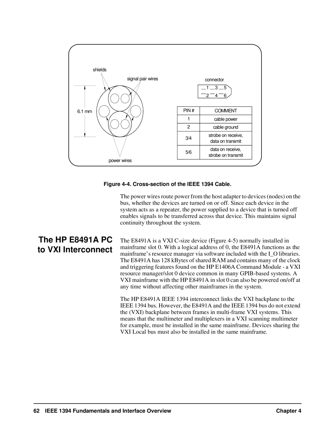
Figure 4-4. Cross-section of the IEEE 1394 Cable.
The HP E8491A PC to VXI Interconnect
The power wires route power from the host adapter to devices (nodes) on the bus, whether the devices are turned on or off. Since each device in the system acts as a repeater, the power supplied to a device that is turned off enables signals to be transferred across that device. This maintains signal continuity throughout the system.
The E8491A is a VXI
The HP E8491A IEEE 1394 interconnect links the VXI backplane to the IEEE 1394 bus. However, the E8491A and the IEEE 1394 bus do not extend the (VXI) backplane between frames in
62 IEEE 1394 Fundamentals and Interface Overview | Chapter 4 |