// set the trigger source
iprintf(e1412, "TRIG:SOUR TTLT4\n");//trigger line 4
// set the sample count
iprintf(e1412, "SAMP:COUN 10\n");// 10 readings
//initiate the multimeter iprintf(e1412, "INIT\n");
printf("Press ’Enter’ to trigger the voltmeter\n"); getchar ();
//output a trigger pulse on the E8491A ’Trig Out’ connector, the
//trigger is then input to the ’Trig In’ connector via a jumper wire
//and routed to TTL trigger line 4 which triggers the multimeter ixtrig(e8491, I_TRIG_EXT0);
//fetch the readings once the trigger is received
ipromptf(e1412, "FETC?\n", "%,10lf", dcv_rdgs);
//display the readings for (i=0; i<10; i++)
{
printf("%lf\n", dcv_rdgs[i]);
}
//close the device sessions
iclose(e8491);// close SICL interface session iclose(e1412);// close SICL device session
}
Comments
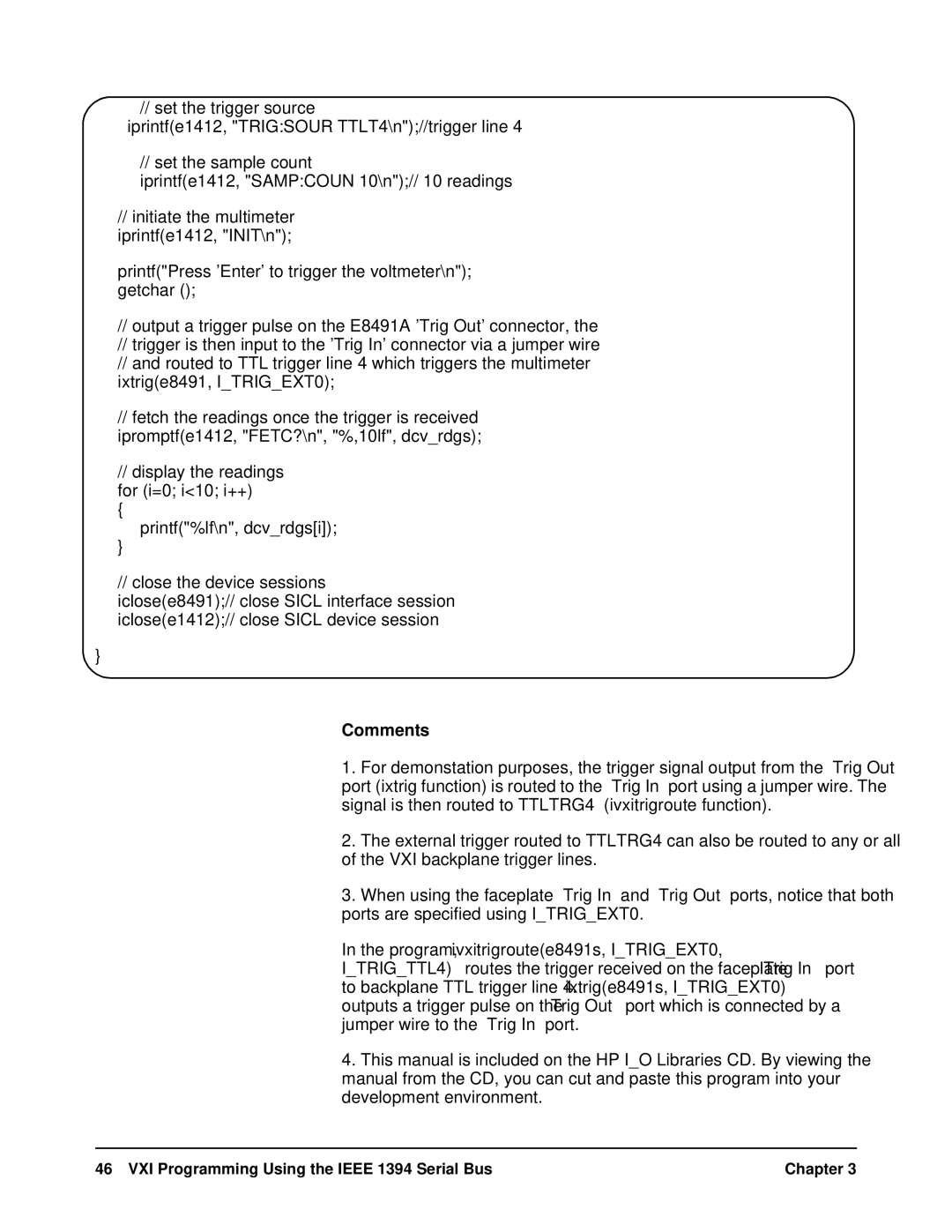
1.For demonstation purposes, the trigger signal output from the ‘Trig Out’ port (ixtrig function) is routed to the ‘Trig In’ port using a jumper wire. The signal is then routed to TTLTRG4 (ivxitrigroute function).
2.The external trigger routed to TTLTRG4 can also be routed to any or all of the VXI backplane trigger lines.
3.When using the faceplate ‘Trig In’ and ‘Trig Out’ ports, notice that both ports are specified using I_TRIG_EXT0.
In the program, ivxitrigroute(e8491s, I_TRIG_EXT0,
I_TRIG_TTL4)routes the trigger received on the faceplate ‘Trig In’ port to backplane TTL trigger line 4. ixtrig(e8491s, I_TRIG_EXT0) outputs a trigger pulse on the ‘ Trig Out’ port which is connected by a jumper wire to the ‘Trig In’ port.
4.This manual is included on the HP I_O Libraries CD. By viewing the manual from the CD, you can cut and paste this program into your development environment.
46 VXI Programming Using the IEEE 1394 Serial Bus | Chapter 3 |
