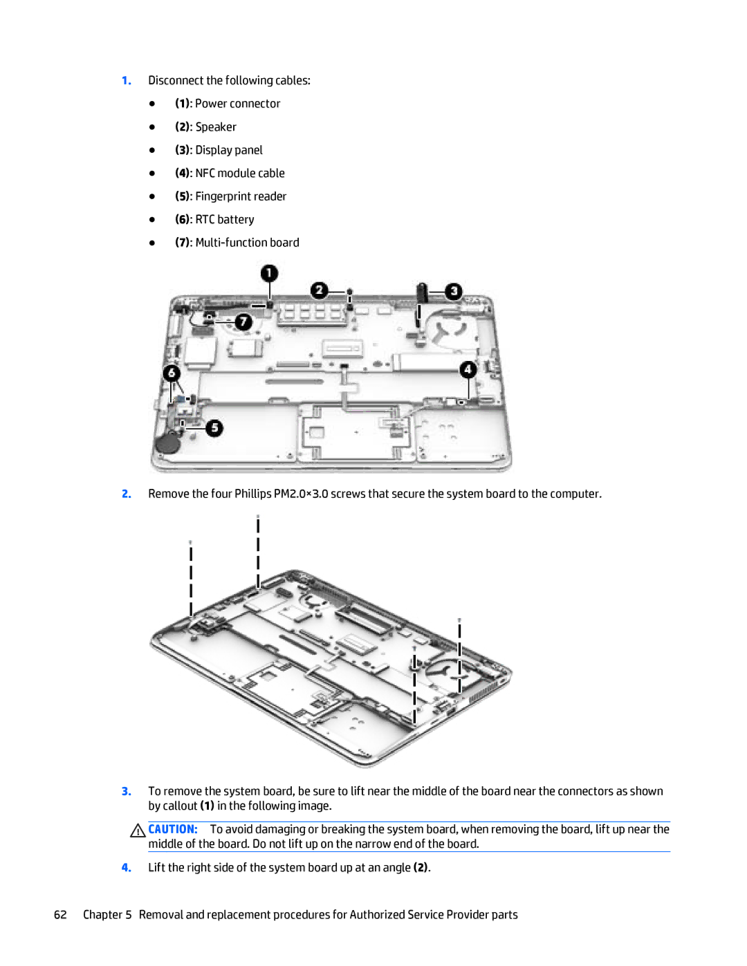
1.Disconnect the following cables:
●(1): Power connector
●(2): Speaker
●(3): Display panel
●(4): NFC module cable
●(5): Fingerprint reader
●(6): RTC battery
●(7):
2.Remove the four Phillips PM2.0×3.0 screws that secure the system board to the computer.
3.To remove the system board, be sure to lift near the middle of the board near the connectors as shown by callout (1) in the following image.
CAUTION: To avoid damaging or breaking the system board, when removing the board, lift up near the middle of the board. Do not lift up on the narrow end of the board.
4.Lift the right side of the system board up at an angle (2).
62 Chapter 5 Removal and replacement procedures for Authorized Service Provider parts