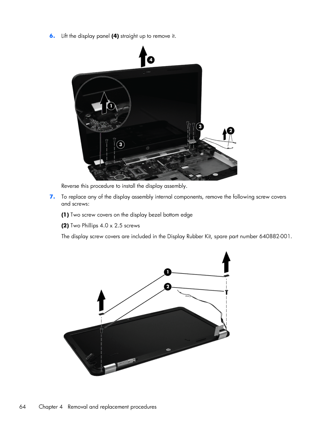
6.Lift the display panel (4) straight up to remove it.
Reverse this procedure to install the display assembly.
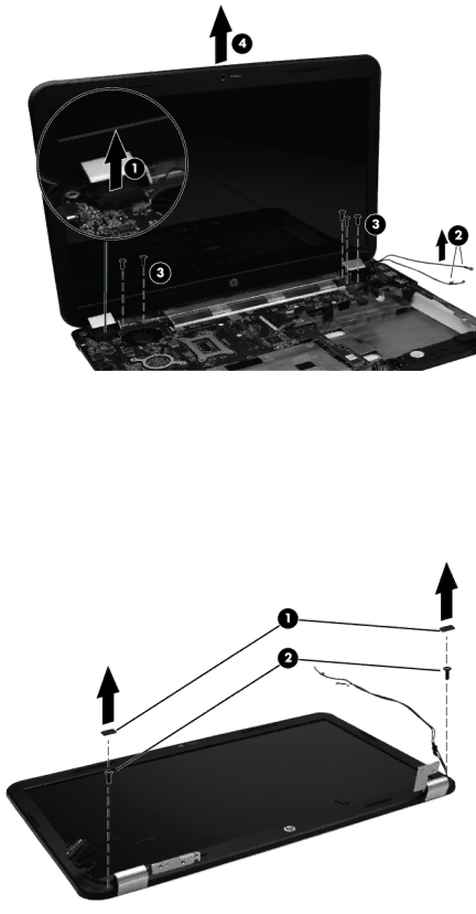
7.To replace any of the display assembly internal components, remove the following screw covers and screws:
(1)Two screw covers on the display bezel bottom edge
(2)Two Phillips 4.0 x 2.5 screws
The display screw covers are included in the Display Rubber Kit, spare part number
64 | Chapter 4 Removal and replacement procedures |