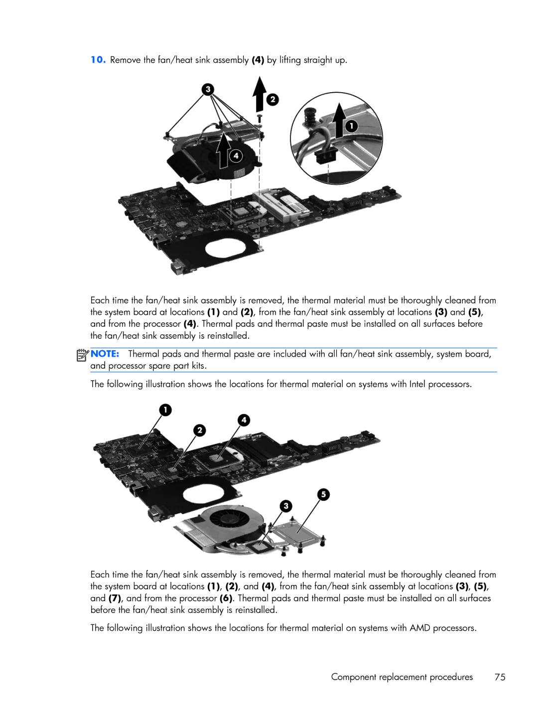
10.Remove the fan/heat sink assembly (4) by lifting straight up.
Each time the fan/heat sink assembly is removed, the thermal material must be thoroughly cleaned from the system board at locations (1) and (2), from the fan/heat sink assembly at locations (3) and (5), and from the processor (4). Thermal pads and thermal paste must be installed on all surfaces before the fan/heat sink assembly is reinstalled.
![]()
![]()
![]()
![]() NOTE: Thermal pads and thermal paste are included with all fan/heat sink assembly, system board, and processor spare part kits.
NOTE: Thermal pads and thermal paste are included with all fan/heat sink assembly, system board, and processor spare part kits.
The following illustration shows the locations for thermal material on systems with Intel processors.
Each time the fan/heat sink assembly is removed, the thermal material must be thoroughly cleaned from the system board at locations (1), (2), and (4), from the fan/heat sink assembly at locations (3), (5), and (7), and from the processor (6). Thermal pads and thermal paste must be installed on all surfaces before the fan/heat sink assembly is reinstalled.
The following illustration shows the locations for thermal material on systems with AMD processors.
Component replacement procedures | 75 |