Installation
Serial Port Settings
The ![]()
![]() (COM1 and COM2) icons represent the serial ports of the video network station. Use these icons when an
(COM1 and COM2) icons represent the serial ports of the video network station. Use these icons when an
Note
If a serial port has the Click “Save” icon enabled, the video network station reboots and alarm memory contents are erased, so check the alarm memory contents, if necessary, before setting.
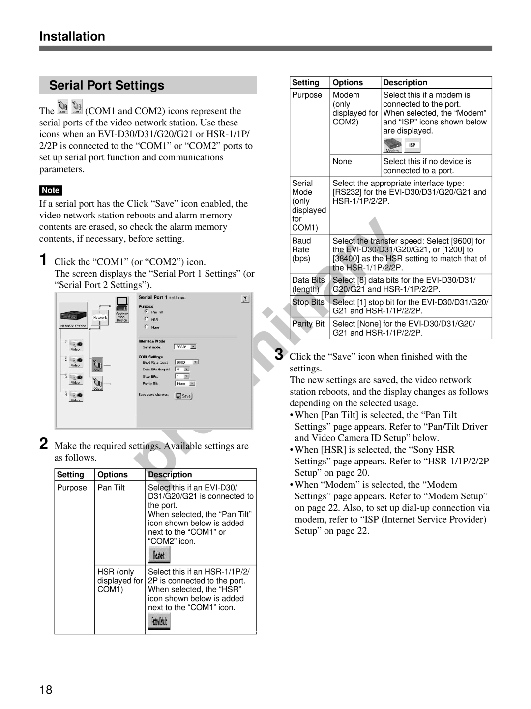
1 Click the “COM1” (or “COM2”) icon.
The screen displays the “Serial Port 1 Settings” (or “Serial Port 2 Settings”).
2 Make the required settings. Available settings are as follows.
Setting | Options | Description |
|
|
|
Purpose | Pan Tilt | Select this if an |
|
| D31/G20/G21 is connected to |
|
| the port. |
|
| When selected, the “Pan Tilt” |
|
| icon shown below is added |
|
| next to the “COM1” or |
|
| “COM2” icon. |
|
|
|
| HSR (only | Select this if an |
| displayed for | 2P is connected to the port. |
| COM1) | When selected, the “HSR” |
|
| icon shown below is added |
|
| next to the “COM1” icon. |
|
|
|
Setting | Options | Description |
|
|
|
Purpose | Modem | Select this if a modem is |
| (only | connected to the port. |
| displayed for | When selected, the “Modem” |
| COM2) | and “ISP” icons shown below |
|
| are displayed. |
|
|
|
| None | Select this if no device is |
|
| connected to a port. |
|
|
|
Serial | Select the appropriate interface type: | |
Mode | [RS232] for the | |
(only | ||
displayed |
|
|
for |
|
|
COM1) |
|
|
|
|
|
Baud | Select the transfer speed: Select [9600] for | |
Rate | the | |
(bps) | [38400] as the HSR setting to match that of | |
| the | |
|
|
|
Data Bits | Select [8] data bits for the | |
(length) | G20/G21 and | |
|
|
|
Stop Bits | Select [1] stop bit for the | |
| G21 and | |
|
|
|
Parity Bit | Select [None] for the | |
| G21 and | |
|
|
|
3 Click the “Save” icon when finished with the settings.
The new settings are saved, the video network station reboots, and the display changes as follows depending on the selected usage.
•When [Pan Tilt] is selected, the “Pan Tilt Settings” page appears. Refer to “Pan/Tilt Driver and Video Camera ID Setup” below.
•When [HSR] is selected, the “Sony HSR Settings” page appears. Refer to
•When “Modem” is selected, the “Modem Settings” page appears. Refer to “Modem Setup” on page 22. Also, to set up
18
