5.Remove the three Phillips 3.0 x 2.0 screws in the battery bay, two Phillips 3.0 x 2.0 screws in the optical drive bay, and ten Phillips 6.0 x 2.5 on the base enclosure.
![]()
![]()
![]()
![]() NOTE: The four screws along the front edge also serve to secure the speakers inside the base enclosure.
NOTE: The four screws along the front edge also serve to secure the speakers inside the base enclosure.
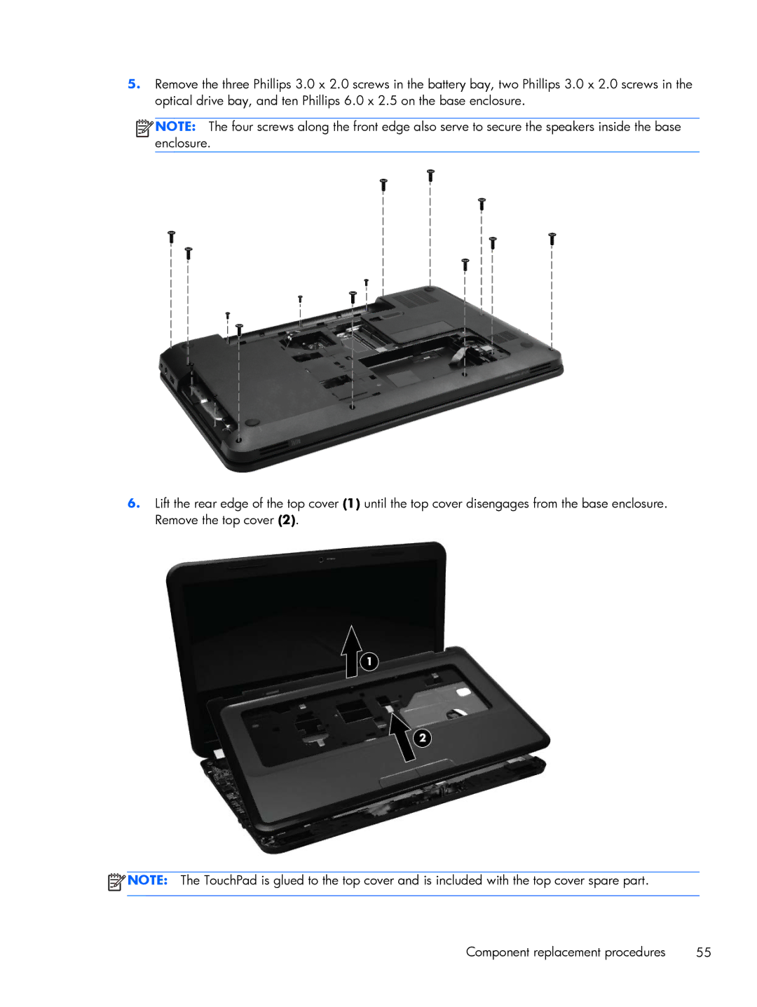
6.Lift the rear edge of the top cover (1) until the top cover disengages from the base enclosure. Remove the top cover (2).
![]() NOTE: The TouchPad is glued to the top cover and is included with the top cover spare part.
NOTE: The TouchPad is glued to the top cover and is included with the top cover spare part.
Component replacement procedures | 55 |