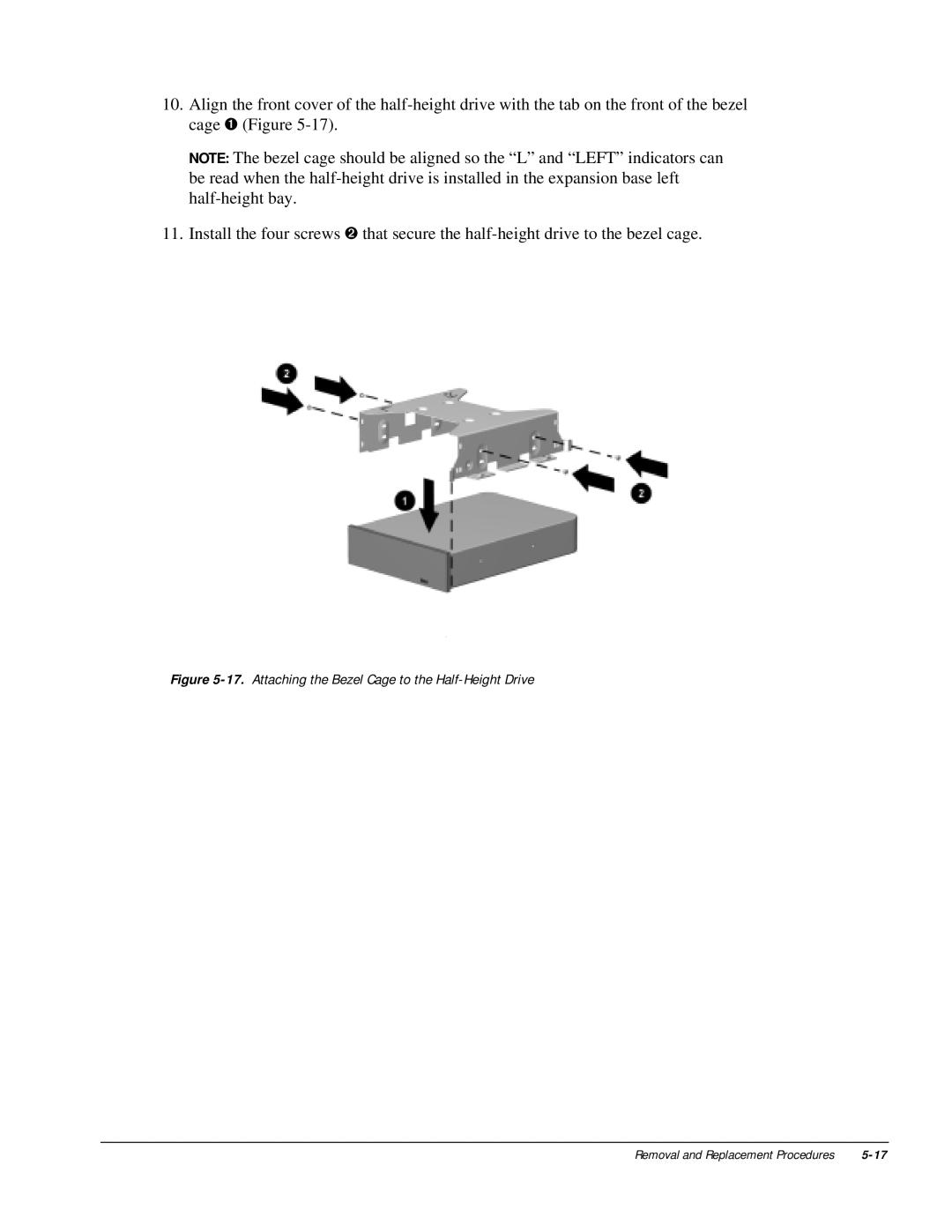
10.Align the front cover of the
NOTE: The bezel cage should be aligned so the “L” and “LEFT” indicators can be read when the
11.Install the four screws ➋ that secure the
Figure 5-17. Attaching the Bezel Cage to the Half-Height Drive
Removal and Replacement Procedures |