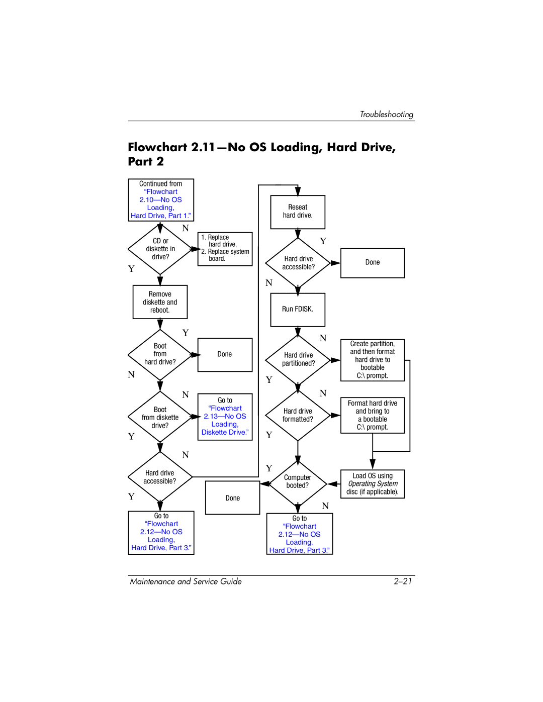
Contents
Maintenance and Service Guide
Page
Contents
3 Illustrated Parts Catalog
4 Removal and Replacement Preliminaries
5 Removal and Replacement Procedures
Page
Product Description
1.1Features
Page
1.2 Resetting the Computer
1.3 Power Management
1.4 External Components
Front Components (Continued)
Page
Right-SideComponents
Left-SideComponents
Left-SideComponents (Continued)
Page
Rear Panel Components
Page
Standard Keyboard Components
Top Components
Top Components (Continued)
Page
Pointing Device Components
Bottom Components
Bottom Components (Continued)
1.5 Design Overview
Troubleshooting
2.1Computer Setup
2.Select the Files, Security, Diagnostics, or System Configuration menu
File > Ignore Changes and Exit
File > Save Changes and Exit
Computer Setup Defaults
Computer Setup Menus
Security Menu
Security Menu (Continued)
Diagnostics Menu
System Configuration Menu
System Configuration Menu (Continued)
Page
2.2 Troubleshooting Flowcharts
Flowchart 2.1—InitialTroubleshooting
Flowchart 2.2—NoPower, Part
Flowchart 2.3—NoPower, Part
Flowchart 2.4—NoPower, Part
Flowchart 2.5—NoPower, Part
Flowchart 2.6—NoVideo, Part
Flowchart 2.7—NoVideo, Part
Flowchart 2.8—NonfunctioningDocking Device (if applicable)
Flowchart 2.9—NoOperating System (OS) Loading
Flowchart 2.10—NoOS Loading, Hard Drive, Part
Flowchart 2.11—NoOS Loading, Hard Drive, Part
Flowchart 2.12—NoOS Loading, Hard Drive, Part
Flowchart 2.13—NoOS Loading, Diskette Drive
Flowchart 2.14—NoOS Loading, Optical Drive
Flowchart 2.15—NoAudio, Part
Flowchart 2.16—NoAudio, Part
Flowchart 2.17—NonfunctioningDevice
Flowchart 2.18—NonfunctioningKeyboard
Flowchart 2.19—NonfunctioningPointing Device
Flowchart 2.20—NoNetwork/Modem Connection
Illustrated Parts Catalog
3.1 Serial Number Location
3.2 Computer Major Components
Spare Parts: Computer Major Components
Page
Spare Parts: Computer Major Components (Continued)
Page
Page
Page
Page
Page
Page
Page
Page
Page
Page
3.3 Display Assembly Components
Display Assembly Components
Spare Part Number Information
3.4 Plastics Kit
3.5 Cable Kit
3.6 Mass Storage Devices
3.7 Miscellaneous (Not Illustrated)
Spare Part Information (Continued)
Page
3.8 Sequential Part Number Listing
Sequential Part Number Listing (Continued)
Page
Page
Page
Page
Page
Page
Page
Page
Page
Removal and Replacement Preliminaries
4.1 Tools Required
4.2 Service Considerations
Plastic Parts
Cables and Connectors
4.3Preventing Damage to Removable Drives
4.4 Preventing Electrostatic Damage
4.5Packaging and Transporting Precautions
4.6 Workstation Precautions
4.7Grounding Equipment and Methods
Typical Electrostatic Voltage Levels
Static-ShieldingMaterials
Removal and Replacement Procedures
5.1 Serial Number
5.2 Disassembly Sequence Chart
Disassembly Sequence Chart (Continued)
5.3Preparing the Computer for Disassembly
Page
5.4 Hard Drive
Page
Page
Page
5.5 Computer Feet
5.6 Bluetooth Module
5.7 External Memory Module
Page
5.8 Mini Card Module
Spare Part Number Information (Continued)
Page
5.9 RTC Battery
5.10 Optical Drive
Page
5.11 Keyboard
Keyboard Spare Part Number Information (Continued)
Page
Page
5.12 Internal Memory Module
Page
5.13 TouchPad
Page
Page
Page
5.14 Modem Module
Page
5.15 Switch Cover
Page
5.16 LED Board
5.17 Fan Assembly
5.18 Processor Heat Sink
Page
5.19 Processor
Page
5.20 Video Board Heat Sink
Page
Page
Page
5.21 Video Board
Page
5.22 Display Assembly
Page
Page
Page
Display Assembly Subcomponents
Page
Page
Page
Page
Page
Page
Page
Page
Page
Page
Page
Page
5.23 Top Cover
Page
Page
5.24 Speaker
Page
5.25 System Board
Page
Page
Page
Page
Page
Page
5.26 USB/Audio Board
Page
Page
5.27 PC Card/Smart Card Assembly
Page
Page
Specifications
Computer (Continued)
17.0-inch,WUXGA+WVA
17.0-inch,WSXGA+WVA
17.0-inch,WXGA+WVA
Hard Drives
Primary 8-cell, Li-IonBattery Pack
DVD±RW and CD-RWCombo Drive
DVD±RW and CD-RWCombo Drive (Continued)
DVD/CD-RWCombo Drive
DVD/CD-RWCombo Drive (Continued)
System DMA
System Interrupts
System Interrupts (Continued)
System I/O Addresses
System I/O Addresses (Continued)
Page
System Memory Map
Screw Listing
Table A-2
Phillips PM2.5×17.0 Screw
Table A-3
Phillips PM2.5×13.0 Spring-LoadedScrew
Table A-4
Phillips PM2.5×4.0 Screw
Table A-5
Phillips PM2.0×4.0 Screw
Phillips PM2.0×4.0 Screw (Continued)
Page
Page
Page
Table A-6
Torx8 T8M2.5×9.0 Screw
Torx8 T8M2.5×9.0 Screw (Continued)
Page
Table A-7
Torx8 T8M2.5×4.0 Screw
Torx8 T8M2.5×4.0 Screw (Continued)
Page
Page
Page
Page
Table A-8
Torx8 T8M2.5×19.0 Screw
Table A-9
Torx8 T8M2.5×7.0 Screw
Torx8 T8M2.5×7.0 Screw (Continued)
Page
Page
Table A-10
Phillips PM2.5×7.0 Screw
Phillips PM2.5×7.0 Screw (Continued)
Page
Table A-11
Hex Socket HM5.0×9.0 Screw Locks
Table A-12
Phillips PM2.0×6.0 Screws
Software Backup and
Recovery
Backup
Safeguarding Your Data
Backing Up the System
Backing Up Specific Files or Folders
Backing Up the Entire Hard Drive
Backing Up Modifications Made to the System
Scheduling Backups
Recovery
Creating Recovery Discs
(Highly Recommended)
Performing a Recovery
Performing a Recovery from the Recovery Discs
Performing a Recovery from the Hard Drive
Display Component Recycling
Page
Page
Page
Page
Page
Page
Page
Page
Page
Page
Page
Page
Page
Connector Pin Assignments
Table D-2
Audio-In(Microphone)
Table D-3
Universal Serial Bus
Table D-4
S-Video-Out
Table D-5
External Monitor
Table D-6
RJ-11(Modem)
Table D-7
RJ-45(Network)
Power Cord Set Requirements
3-ConductorPower Cord Set
General Requirements
Country-SpecificRequirements
3-ConductorPower Cord Set Requirements (Continued)
Index