Installation
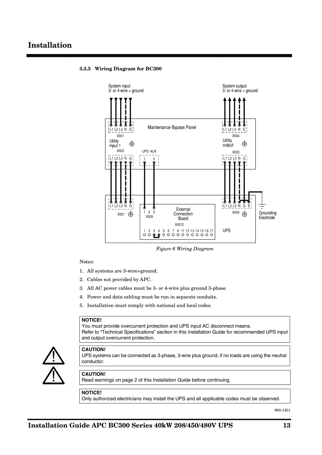
3.3.3 Wiring Diagram for BC300
System input
3- or
L1 L2 L3 N G | Maintenance Bypass Panel |
| |
X001 |
|
System output
3- or
L1 L2 L3 N G
X004
Utility input 1
X002
L1 L2 L3 N G
L1 L2 L3 N G
X001
UPS AUX
1 2 3
1 | 2 | 3 | External | |
Connection | ||||
|
|
|
X009 | Board |
| |
| X0012 |
1 2 3 4 5 6 7 8 11 12 13 14 15 16 17
Utility output
X003
L1 L2 L3 N G
L1 L2 L3 N G E
X004Grounding Electrode
UPS
Figure 6 Wiring Diagram
Notes:
1.All systems are
2.Cables not provided by APC.
3.All AC power cables must be 3- or
4.Power and data cabling must be run in separate conduits.
5.Installation must comply with national and local codes.
NOTICE!
You must provide overcurrent protection and UPS input AC disconnect means.
Refer to “Technical Specifications” section in this Installation Guide for recommended UPS input and output overcurrent protection.
CAUTION!
UPS systems can be connected as
CAUTION!
Read warnings on page 2 of this Installation Guide before continuing.
NOTICE!
Only authorized electricians may install the UPS and all applicable codes must be observed.
| |
|
|
Installation Guide APC BC300 Series 40kW 208/450/480V UPS | 13 |