Installation
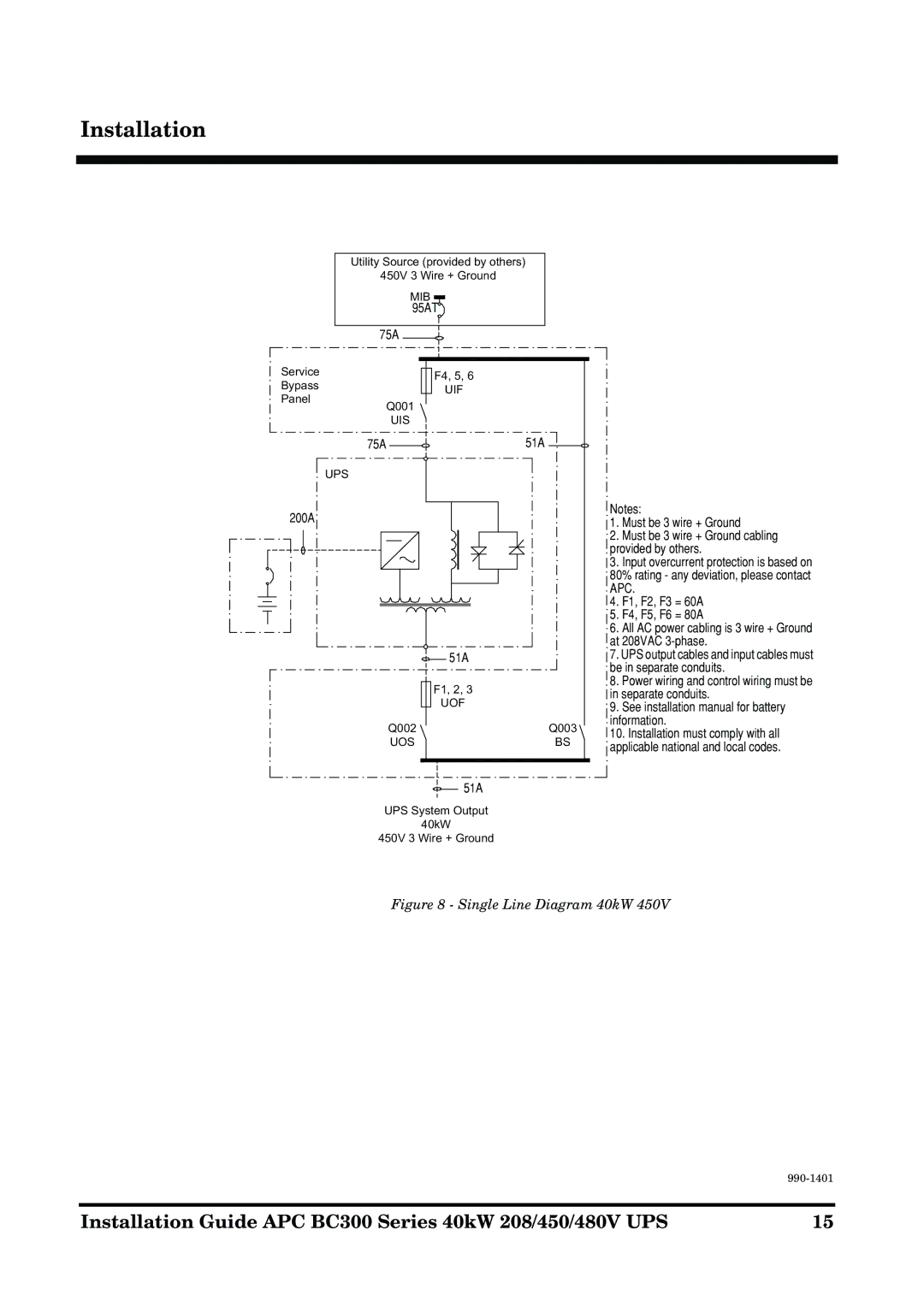
Utility Source (provided by others)
450V 3 Wire + Ground
MIB ![]()
95AT
75A
Service | F4, 5, 6 | |
Bypass | ||
UIF | ||
Panel | ||
| ||
Q001 |
| |
UIS |
| |
75A | 51A |
UPS
200A
51A
F1, 2, 3
UOF
Q002 | Q003 |
UOS | BS |
51A
UPS System Output
40kW
450V 3 Wire + Ground
Notes:
1.Must be 3 wire + Ground
2.Must be 3 wire + Ground cabling provided by others.
3.Input overcurrent protection is based on 80% rating - any deviation, please contact APC.
4.F1, F2, F3 = 60A
5.F4, F5, F6 = 80A
6.All AC power cabling is 3 wire + Ground at 208VAC
7.UPS output cables and input cables must be in separate conduits.
8.Power wiring and control wiring must be in separate conduits.
9.See installation manual for battery information.
10.Installation must comply with all applicable national and local codes.
Figure 8 - Single Line Diagram 40kW 450V
| |
|
|
Installation Guide APC BC300 Series 40kW 208/450/480V UPS | 15 |