Maintenance & Service Guide
Maintenance & Service Guide
About This Book
Iv About This Book
Table of contents
Serial ATA Sata Drive Guidelines and Features
Removal and Replacement Procedures Microtower Chassis
126
196
Page
Product Features
Feature Overview
Microtower Components
Small Form Factor Components
Activating and customizing the software in Windows
Activating and Customizing the Software
Activating the Windows operating system
Installing or upgrading device drivers
Downloading Windows 7 updates
Customizing the monitor display
Downloading Windows 8 updates
Click Settings Change PC Settings
Computer Setup F10 Utility
Computer Setup F10 Utilities
Using Computer Setup F10 Utilities
1Computer Setup F10 Utility
Computer Setup-File
2Computer Setup-File
Sata Defaults
Computer Setup-Storage
3Computer Setup-Storage
OptionDescription
Sata Emulation
Removable Media Boot
Storage Options ESATA Port
Max eSATA Speed
Shortcut to Temporarily Override Boot Order
Boot Order
DPS Self-Test
Computer Setup-Security
4Computer Setup-Security
Slot Security
Network Boot
Master Boot Record
System IDs
System Security
Configuration
Secure Boot
DriveLock Security
Computer Setup-Power
5Computer Setup-Power
6Computer Setup-Advanced for advanced users
Computer Setup-Advanced
Option Heading Power-On Options
Bus Options
Bios Power-On
Onboard Devices
Device Options
VGA Configuration
Recovering the Configuration Settings
AMT Configuration
Microtower Chassis Spare Parts
Illustrated parts catalog
Computer Major Components
Power supply, 300W
Description Spare part number Access panel
Front bezel
Description Spare part number
Item Description Spare part number
Cables
Chassis fan
Front I/O and USB assembly
Misc Parts
Wlan cover
Description Spare part number Hard drive
Drives
Misc Boards
Optical drive
Wlan modules
Sequential Part Number Listing
Spare part Description Number
Microtower Chassis Spare Parts
For use in Brazil
HP Pro 3505 models
Illustrated parts catalog
Intel Core i7 processor
Power supply
Small Form Factor SFF Chassis Spare Parts
Intel Core i5 processors
Intel Core i3 processors
Intel Pentium Dual-Core processors
Cables
Misc Parts
DVI to VGA adapter not illustrated
Illustrated parts catalog
Small Form Factor SFF Chassis Spare Parts
Sata Hard Drives
Serial ATA Sata Drive Guidelines and Features
Serial ATA Hard Drive Characteristics
Sata Hard Drive Cables
Smart ATA Drives
Generating Static
Routine Care and Disassembly Preparation
Electrostatic Discharge Information
Relative Humidity Event 55% 40% 10%
Static Shielding Protection Levels
Preventing Electrostatic Damage to Equipment
Personal Grounding Methods and Equipment
Method Voltage
Grounding the Work Area
Recommended Materials and Equipment
Operating Guidelines
General Cleaning Safety Precautions
Cleaning the Computer Case
Routine Care
Cleaning the Keyboard
Cleaning the Monitor
Power Supply Fan
Service Considerations
Cleaning the Mouse
Tools and Software Requirements
Lithium Coin Cell Battery
Cables and Connectors
Hard Drives
Serviceability Features
Removal and Replacement Procedures Microtower Chassis
Preparation for Disassembly
Access Panel
Description Spare part number Access panel 674373-001
Front Bezel
Memory
DDR3-SDRAM DIMMs
Populating Dimm Sockets
Description Socket Color Insertion Order
Removing Memory Modules
Page
Expansion Cards
Model 3410 expansion slots
Slot Type Number of Slots
Expansion slot locations model
Page
Page
Page
Cable Management
Connector Name Connector Color Description
Cable Connections
Drives
Installing Additional Drives
System Board Drive Connections
System Board Connector System Board Label Color
System Board Drive Connections
System Board Drive Connections HP Pro
System Board Drive Connections Model
Yellow
Removing an Optical Drive
Page
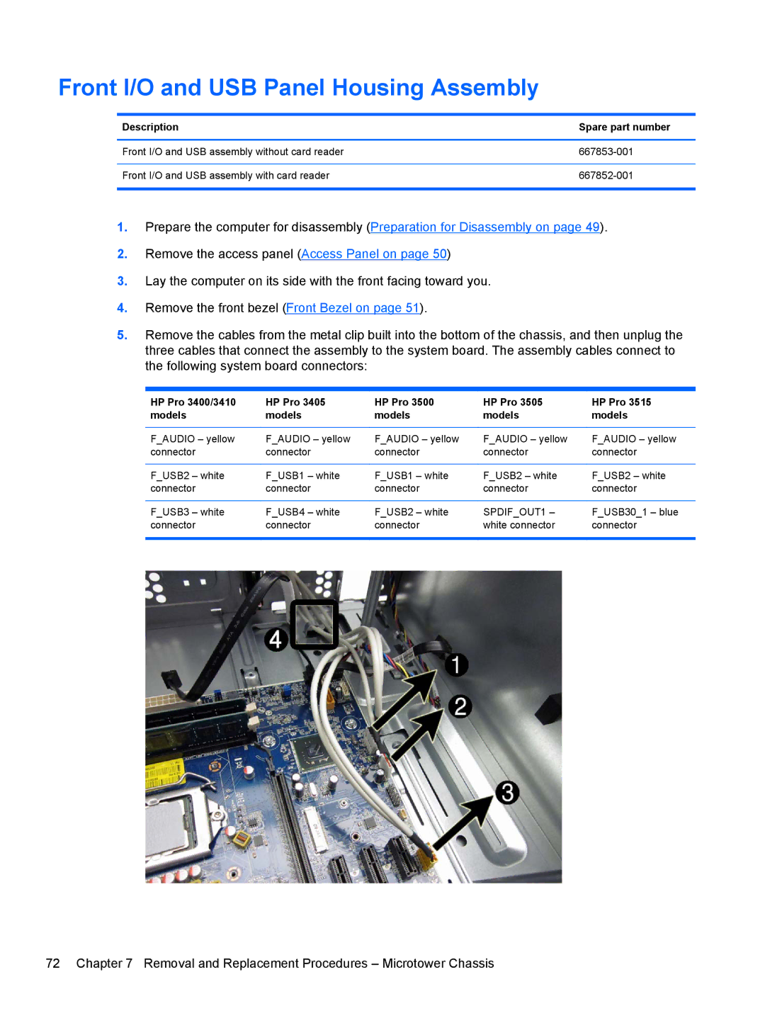
Front I/O and USB Panel Housing Assembly
HP Pro 3400/3410 Models
Page
Power Switch/LED Assembly
Remove the optical drive Removing an Optical Drive on
Page
System Fan
Page
Fan Sink Assembly
Description Spare part number Intel Core i7 processors
Processor
Intel Celeron processors
Remove the fan sink Fan Sink Assembly on
Page
Power Supply
System Board
Page
Battery
Page
Preparation for Disassembly
Description Spare part number Access panel 656832-001
Page
Description Spare part number Front bezel 656835-001
GB, PC3-10600 585157-001 635803-001 635802-001
Description Socket Color
Removing DIMMs
Page
Page
Expansion Card
Description Spare part number Graphics cards
PCI
Page
Page
Cable Management
Sysfan
Drive Positions
Removing Drives
Page
Removing the Hard Drive
Page
Page
Page
Power Switch
Page
Front USB Assembly
Page
Page
Fan Assembly
Description Spare part number Fan 656834-001
Page
Fan Sink
Description Spare part number Fan sink 657402-001
Page
2600S 2.7 GHz, 8-MB L3 cache, 65W 638419-001
Page
Power supply, 220W 656722-001 Power supply, 270W 665224-001
Page
System Board
Page
Battery
Page
Japanese Power Cord Requirements
Power Cord Set Requirements
General Requirements
Country-Specific Requirements
Country Accrediting Agency
Post Error Messages
Post Numeric Codes and Text Messages
Table B-1Numeric Codes and Text Messages
Appendix B Post Error Messages
Verify monitor is attached and turned
Replace diskette drive
Select File Save Changes and Exit
Test under Storage DPS Self-test
Options Sata Emulation to IDE,
Security Drivelock Security. For each
Appendix B Post Error Messages
Bios
Occurred prior to the ME firmware update
Table B-2Diagnostic Front Panel LEDs and Audible Codes
Activity Beeps Possible Cause Recommended Action
Desktop Management Guide for more
Appendix B Post Error Messages
Password Security and Resetting
Cmos
Resetting the Password Jumper
Clearing and Resetting the Cmos
Page
Troubleshooting Without Diagnostics
Safety and Comfort Before You Call for Technical Support
Helpful Hints
Refer to Helpful Hints on page 145 in this guide
Page
Computer date and time display is incorrect Cause Solution
Solving General Problems
Table D-1Solving General Problems
Computer will not respond to keyboard or mouse Cause
Poor performance Cause Solution
There is no sound or sound volume is too low Cause Solution
Cannot remove computer cover or access panel Cause
Advanced Device Options
All apps icon
Under Windows System, click Run
Cause Solution
Table D-2Solving Power Problems
Solving Power Problems
Power supply shuts down intermittently Cause Solution
Some models, is set to the appropriate voltage. Proper
Solving Hard Drive Problems
Table D-3Solving Hard Drive Problems
Storage Boot Order
Nonsystem disk/NTLDR missing message Cause Solution
Computer will not boot from hard drive Cause Solution
Device Configuration
Computer seems to be locked up Cause Solution
Table D-4Solving Media Card Reader Problems
Solving Media Card Reader Problems
Can not write to the media card Cause
Computer’s software is used to safely eject the card
Blank screen no video Cause Solution
Solving Display Problems
Table D-5Solving Display Problems
Adjust screen resolution
Dim characters Cause Solution
No Connection, Check Signal Cable displays on screen Cause
Image is not centered Cause Solution
Select ImageControl/ Horizontal Position or Vertical
Out of Range displays on screen Cause
Certain typed symbols do not appear correct Cause
Solving Audio Problems
Table D-6Solving Audio Problems
There is no sound or sound volume is too low Cause
Sound from headphones is not clear or muffled Cause
Line-in jack is not functioning properly Cause
Printer will not print Cause Solution
Solving Printer Problems
Table D-7Solving Printer Problems
Printer will not turn on Cause Solution
Printer prints garbled information Cause Solution
Solving Keyboard and Mouse Problems
Table D-8Solving Keyboard Problems
Table D-9Solving Mouse Problems
Enter
Control Panel , and then select Device Manager
Solving Hardware Installation Problems
Table D-10Solving Hardware Installation Problems
Security USB Security
Computer will not start Cause Solution
Solving Network Problems
Table D-11Solving Network Problems
Network status link light never flashes Cause Solution
Manager
Diagnostics reports a failure Cause
Solving Memory Problems
Memory count during Post is wrong Cause Solution
Table D-12Solving Memory Problems
Out of memory error Cause Solution
Insufficient memory error during operation Cause Solution
Table D-13Solving Processor Problems
Solving Processor Problems
Solving CD-ROM and DVD Problems
Table D-14Solving CD-ROM and DVD Problems
Security Network Boot
Movie will not play in the DVD drive Cause Solution
Cannot eject compact disc tray-load unit Cause
USB flash drive not found identified Cause Solution
Solving USB Flash Drive Problems
Table D-15Solving USB Flash Drive Problems
System will not boot from USB flash drive Cause Solution
Ports are set to Enabled in Security USB Security
Solving Front Panel Component Problems
Solving Internet Access Problems
Unable to connect to the Internet Cause Solution
Select Start Control Panel
Click Internet Options
Solving Software Problems
Solving Software Problems
Contacting Customer Support
HP PC Hardware Diagnostics
Why run HP PC Hardware Diagnostics
How to access and run HP PC Hardware Diagnostics
Downloading HP PC Hardware Diagnostics to a USB device
System Restore
Backup and Recovery
Restoring and recovering in Windows
System Recovery
System Recovery when Windows is responding
System Recovery when Windows is not responding
Creating recovery media
Using recovery media
Backup and recovery in Windows
Backing up your information
Performing a system recovery
Using the Windows recovery tools
Using f11 recovery tools
Specifications
Table G-1Specifications
SFF Specifications
Table G-2Specifications
Index
Cmos
LEDs
Sata