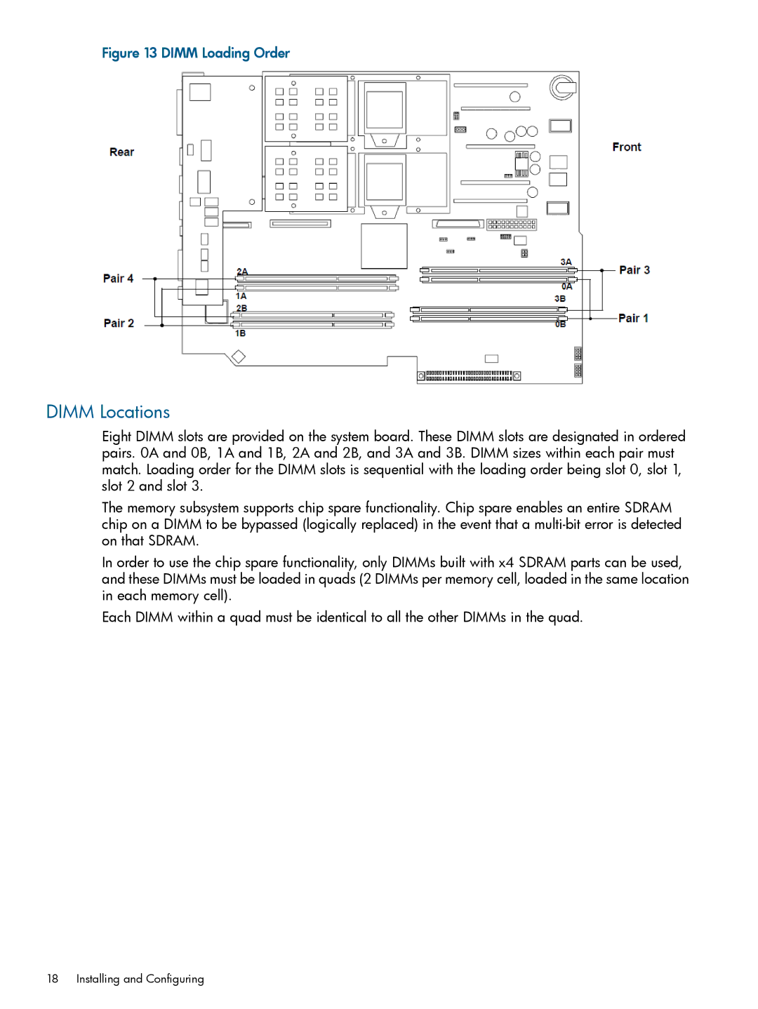
Figure 13 DIMM Loading Order
DIMM Locations
Eight DIMM slots are provided on the system board. These DIMM slots are designated in ordered pairs. 0A and 0B, 1A and 1B, 2A and 2B, and 3A and 3B. DIMM sizes within each pair must match. Loading order for the DIMM slots is sequential with the loading order being slot 0, slot 1, slot 2 and slot 3.
The memory subsystem supports chip spare functionality. Chip spare enables an entire SDRAM chip on a DIMM to be bypassed (logically replaced) in the event that a
In order to use the chip spare functionality, only DIMMs built with x4 SDRAM parts can be used, and these DIMMs must be loaded in quads (2 DIMMs per memory cell, loaded in the same location in each memory cell).
Each DIMM within a quad must be identical to all the other DIMMs in the quad.
18 Installing and Configuring