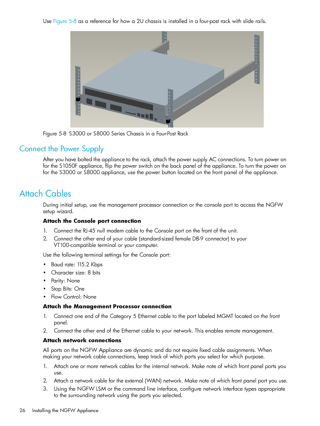
Use Figure
Figure 5-8 S3000 or S8000 Series Chassis in a Four-Post Rack
Connect the Power Supply
After you have bolted the appliance to the rack, attach the power supply AC connections. To turn power on for the S1050F appliance, flip the power switch on the back panel of the appliance. To turn the power on for the S3000 or S8000 appliance, use the power button located on the front panel of the appliance.
Attach Cables
During initial setup, use the management processor connection or the console port to access the NGFW setup wizard.
Attach the Console port connection
1.Connect the
2.Connect the other end of your cable
Use the following terminal settings for the Console port:
•Baud rate: 115.2 Kbps
•Character size: 8 bits
•Parity: None
•Stop Bits: One
•Flow Control: None
Attach the Management Processor connection
1.Connect one end of the Category 5 Ethernet cable to the port labeled MGMT located on the front panel.
2.Connect the other end of the Ethernet cable to your network. This enables remote management.
Attach network connections
All ports on the NGFW Appliance are dynamic and do not require fixed cable assignments. When making your network cable connections, keep track of which ports you select for which purpose.
1.Attach one or more network cables for the internal network. Make note of which front panel ports you use.
2.Attach a network cable for the external (WAN) network. Make note of which front panel port you use.
3.Using the NGFW LSM or the command line interface, configure network interface types appropriate to the surrounding network using the ports you selected.
26 Installing the NGFW Appliance