A Connector and Cable Pinout Specifications
This information provides connector and pinout information for the NGFW Appliance and contains the following topics:
•
•
•”Pluggable Transceivers” on page 30
RJ-45 (COM) Console
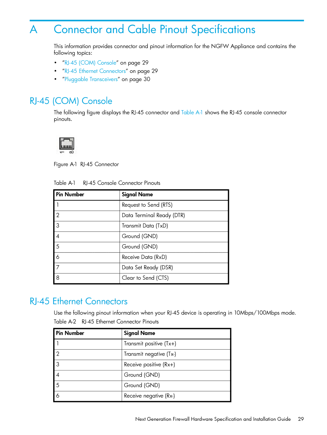
The following figure displays the
Figure A-1 RJ-45 Connector
Table A-1 RJ-45 Console Connector Pinouts
Pin Number | Signal Name |
|
|
1 | Request to Send (RTS) |
|
|
2 | Data Terminal Ready (DTR) |
|
|
3 | Transmit Data (TxD) |
|
|
4 | Ground (GND) |
|
|
5 | Ground (GND) |
|
|
6 | Receive Data (RxD) |
|
|
7 | Data Set Ready (DSR) |
|
|
8 | Clear to Send (CTS) |
|
|
RJ-45 Ethernet Connectors
Use the following pinout information when your
Pin Number | Signal Name |
|
|
1 | Transmit positive (Tx+) |
|
|
2 | Transmit negative |
|
|
3 | Receive positive (Rx+) |
|
|
4 | Ground (GND) |
|
|
5 | Ground (GND) |
|
|
6 | Receive negative |
|
|
Next Generation Firewall Hardware Specification and Installation Guide 29
