IMPORTANT: Be sure there is a blade in Bay 1. See Figure
Figure 1-2 Enclosure Bay Numbering
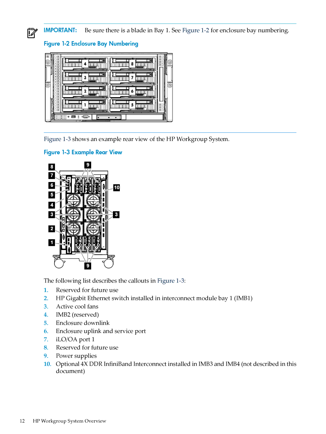
Figure 1-3 shows an example rear view of the HP Workgroup System.
Figure 1-3 Example Rear View
The following list describes the callouts in Figure
1.Reserved for future use
2.HP Gigabit Ethernet switch installed in interconnect module bay 1 (IMB1)
3.Active cool fans
4.IMB2 (reserved)
5.Enclosure downlink
6.Enclosure uplink and service port
7.iLO/OA port 1
8.Reserved for future use
9.Power supplies
10.Optional 4X DDR InfiniBand Interconnect installed in IMB3 and IMB4 (not described in this document)
12 HP Workgroup System Overview