4 HP BIOS
BIOS Addresses
BIOS Addresses
This section provides a summary of the main features of the HP system BIOS. This is software that provides an interface between the computer hardware and the operating system.
The procedure for updating the System ROM firmware is described on page 50.
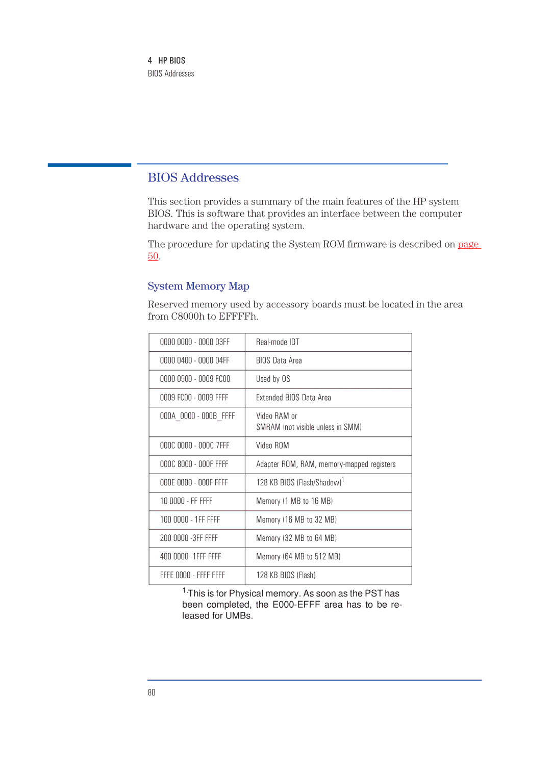
System Memory Map
Reserved memory used by accessory boards must be located in the area from C8000h to EFFFFh.
0000 0000 - 0000 03FF | ||
|
| |
0000 0400 - 0000 04FF | BIOS Data Area | |
|
| |
0000 0500 - 0009 FC00 | Used by OS | |
|
| |
0009 FC00 - 0009 FFFF | Extended BIOS Data Area | |
|
| |
000A_0000 - 000B_FFFF | Video RAM or | |
|
| SMRAM (not visible unless in SMM) |
|
| |
000C 0000 - 000C 7FFF | Video ROM | |
|
| |
000C 8000 - 000F FFFF | Adapter ROM, RAM, | |
|
| |
000E 0000 - 000F FFFF | 128 KB BIOS (Flash/Shadow)1 | |
|
| |
10 0000 - FF FFFF | Memory (1 MB to 16 MB) | |
|
|
|
100 0000 | - 1FF FFFF | Memory (16 MB to 32 MB) |
|
|
|
200 0000 | Memory (32 MB to 64 MB) | |
|
|
|
400 0000 |
| Memory (64 MB to 512 MB) |
|
| |
FFFE 0000 - FFFF FFFF | 128 KB BIOS (Flash) | |
|
|
|
1.This is for Physical memory. As soon as the PST has been completed, the
80