|
|
|
| FUNCTIONAL | DESCRIPTION | |||||
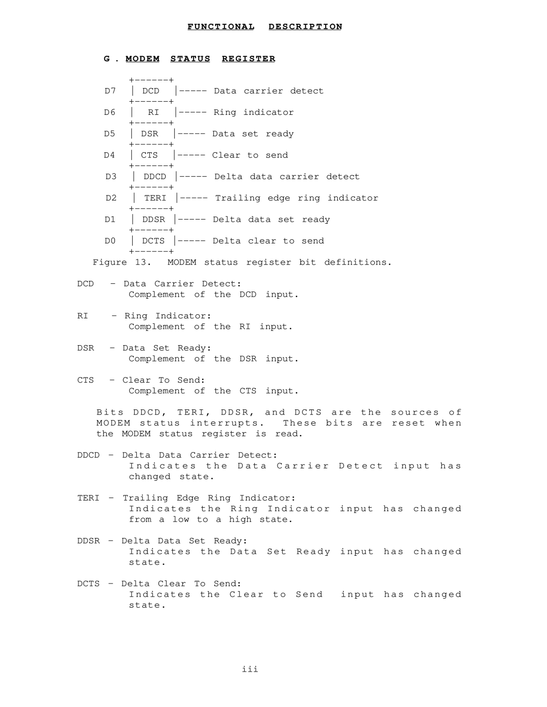
| G . MODEM | STATUS | REGISTER |
|
|
| ||||
|
| + |
|
|
|
|
|
| ||
| D7 | DCD | Data | carrier detect |
| |||||
|
| + |
|
|
|
|
|
| ||
| D6 | RI | Ring | indicator |
|
| ||||
|
| + |
|
|
|
|
|
| ||
| D5 | DSR | Data set | ready |
|
| ||||
|
| + |
|
|
|
|
|
| ||
| D4 | CTS | Clear | to | send |
|
| |||
|
| + |
|
|
|
|
|
| ||
| D3 | DDCD | Delta | data | carrier | detect | ||||
|
| + |
|
|
|
|
|
| ||
| D2 | TERI | Trailing | edge | ring | indicator | ||||
|
| + |
|
|
|
|
|
| ||
| D1 | DDSR | Delta | data | set | ready | ||||
|
| + |
|
|
|
|
|
| ||
| D0 | DCTS | Delta | clear | to | send |
| |||
|
| + |
|
|
|
|
|
| ||
Figure 13. MODEM status register bit definitions. | ||||||||||
DCD | - | Data Carrier Detect: |
|
|
|
|
| |||
|
| Complement of the DCD input. |
| |||||||
RI | - | Ring Indicator: |
|
|
|
|
|
| ||
|
| Complement of the RI input. |
|
| ||||||
DSR | - | Data Set Ready: |
|
|
|
|
|
| ||
|
| Complement of the DSR input. |
| |||||||
CTS | - | Clear To Send: |
|
|
|
|
|
| ||
|
| Complement of | the CTS | input. |
| |||||
Bits DDCD, TERI, DDSR, and DCTS are the sources of MODEM status interrupts . These bits are reset when the MODEM status register is read.
DDCD - Delta Data Carrier Detect:
I n d i c a t e s t h e D a t a C a r r i e r D e t e c t i n p u t h a s changed state.
TERI - Trailing Edge Ring Indicator:
Indicates the Ring Indicator input has changed from a low to a high state.
DDSR - Delta Data Set Ready:
Indicates the Data Set Ready input has changed state.
DCTS - Delta Clear To Send:
Indicates the Clear to Send input has changed state.
iii