OUTPUT CONFIGURATIONS
The other function of J2 and J3 is to configure the communication channel in half or full duplex mode. Half duplex operation is achieved by connecting pins 4 and 8 o f t h e j u m p e r b l o c k ( f i g u r e 2 3 ) . T h i s a l l o w s t h e transmitter to be enabled and disabled using the data t e r m i n a l r e a d y ( D T R ) o u t p u t i n t h e m o d e m c o n t r o l register. Full duplex operation is restored by removing the jumper on pins 4 and 8 (figures 21 and 22).
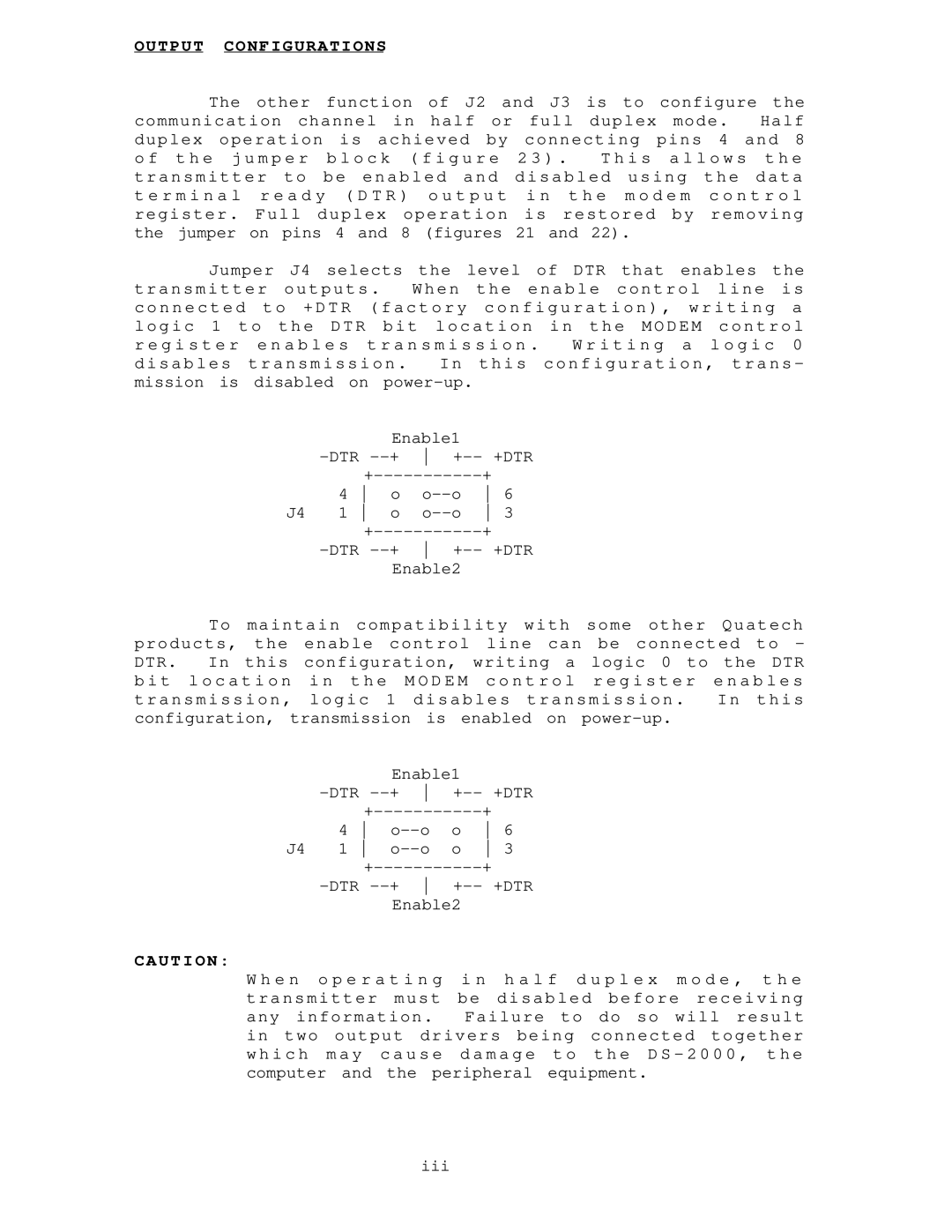
Jumper J4 selects the level of DTR that enables the transmitter outputs . When the enable control line is c o n n e c t e d t o + D T R ( f a c t o r y c o n f i g u r a t i o n ) , w r i t i n g a l o g i c 1 t o t h e D T R b i t l o c a t i o n i n t h e M O D E M c o n t r o l r e g i s t e r e n a b l e s t r a n s m i s s i o n . W r i t i n g a l o g i c 0 disables transmission . In this configuration, trans - mission is disabled on
Enable1
4 o
J4 1 o
Enable2
To maintain compatibility with some other Quatech products, the enable control line can be connected to - DTR. In this configuration, writing a logic 0 to the DTR b i t l o c a t i o n i n t h e M O D E M c o n t r o l r e g i s t e r e n a b l e s transmission, logic 1 disables transmission . In this
configuration, transmission | is enabled on | |||||
|
|
| Enable1 |
| ||
| ||||||
|
| |||||
| 4 | o | 6 | |||
J4 | 1 | o | 3 | |||
|
| |||||
| ||||||
|
|
| Enable2 |
| ||
CAUTION:
W h e n o p e r a t i n g i n h a l f d u p l e x m o d e , t h e transmitter must be disabled before receiving any information. Failure to do so will result in two output drivers being connected together w h i c h m a y c a u s e d a m a g e t o t h e D S - 2 0 0 0 , t h e computer and the peripheral equipment.
iii
