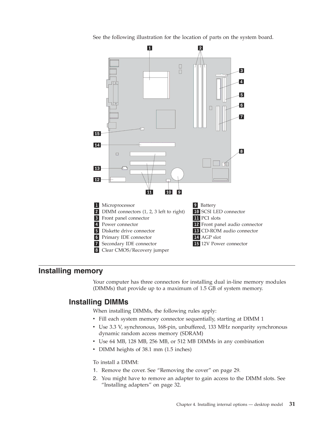
See the following illustration for the location of parts on the system board.
Microprocessor | Battery |
DIMM connectors (1, 2, 3 left to right) | SCSI LED connector |
Front panel connector | PCI slots |
Power connector | Front panel audio connector |
Diskette drive connector | |
Primary IDE connector | AGP slot |
Secondary IDE connector | 12V Power connector |
Clear CMOS/Recovery jumper |
|
Installing memory
Your computer has three connectors for installing dual
Installing DIMMs
When installing DIMMs, the following rules apply:
vFill each system memory connector sequentially, starting at DIMM 1
vUse 3.3 V, synchronous,
vUse 64 MB, 128 MB, 256 MB, or 512 MB DIMMs in any combination
vDIMM heights of 38.1 mm (1.5 inches)
To install a DIMM:
1.Remove the cover. See “Removing the cover” on page 29.
2.You might have to remove an adapter to gain access to the DIMM slots. See “Installing adapters” on page 32.