12 |
| OPTIONAL |
|
|
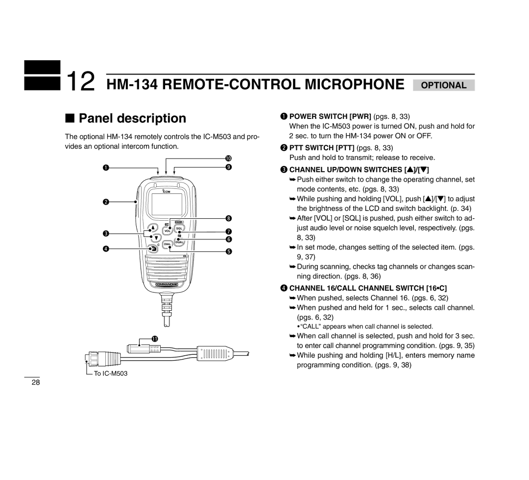
■Panel description
The optional
q POWER SWITCH [PWR] (pgs. 8, 33)
When the
w PTT SWITCH [PTT] (pgs. 8, 33)
q
w
e
r
DIM
VOL
CDIAL
MONI L
SQL
IC
DUAL
!0 o
i
u y
t
Push and hold to transmit; release to receive.
eCHANNEL UP/DOWN SWITCHES [Y]/[Z]
➥Push either switch to change the operating channel, set mode contents, etc. (pgs. 8, 33)
➥While pushing and holding [VOL], push [Y]/[Z] to adjust the brightness of the LCD and switch backlight. (p. 34)
➥After [VOL] or [SQL] is pushed, push either switch to ad- just audio level or noise squelch level, respectively. (pgs. 8, 33)
➥In set mode, changes setting of the selected item. (pgs. 9, 37)
➥During scanning, checks tag channels or changes scan- ning direction. (pgs. 8, 36)
r CHANNEL 16/CALL CHANNEL SWITCH [16•C]
![]() !1
!1
![]() To
To
➥When pushed, selects Channel 16. (pgs. 6, 32)
➥When pushed and held for 1 sec., selects call channel. (pgs. 6, 32)
•“CALL” appears when call channel is selected.
➥When call channel is selected, push and hold for 3 sec. to enter call channel programming condition. (pgs. 9, 35)
➥While pushing and holding [H/L], enters memory name programming condition. (pgs. 9, 38)
28