9 INSTALLATION AND CONNECTIONS
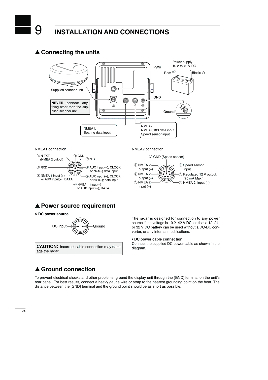
■Connecting the units
Supplied scanner unit
NEVER connect any- thing other than the sup- plied scanner unit.
NMEA1:
Bearing data input
| Power supply | |
PWR | 10.2 to 42 V DC | |
|
| |
| Red: + | Black: _ |
GND
Ground
NMEA2:
NMEA 0183 data input
Speed sensor input
NMEA1 connection | NMEA2 connection |
q N TXT | i GND |
(NMEA 2 output) | u N.C |
w RXD | y AUX input |
| or |
e NMEA 1 input (+) | t AUX input (+); CLOCK |
or AUX input(+); DATA | or N+1(+); data input |
rNMEA 1 input
or AUX input
uGND (Speed sensor)
q NMEA 2 | y Speed sensor |
output (+) | input |
w NMEA 2 | t Regulated 12 V output. |
output | (20 mA Max.) |
e NMEA 2 | r NMEA 2 input |
input (+) |
|
■Power source requirement
DDC power source
DC input ![]()
![]()
![]() Ground
Ground
CAUTION: Incorrect cable connection may dam- age the radar.
The radar is designed for connection to any power source if the voltage is
•DC power cable connection
Connect the supplied DC power cable as shown in the diagram.
■Ground connection
To prevent electrical shocks and other problems, ground the display unit through the [GND] terminal on the unit’s rear panel. For best results, connect a heavy gauge wire or strap to the nearest grounding point on the boat. The distance between the [GND] terminal and the ground point should be as short as possible.
24
