2 PANEL DESCRIPTION
■Screen
@2 |
|
|
|
|
| #9$0 |
@3 |
| @1 |
|
|
| |
|
| M.TUNE |
|
|
| $1 |
| (0.25) | MTUNE |
| TVECT 6M TRAILS |
| |
@4 | 3/4 NM CURS | 0174˚R 0649NM | : | $2 | ||
| 005 | $3 | ||||
@5 | STW157KT | H UP | HDG2530˚T | |||
@6 |
|
|
|
| IR | $4 |
|
|
|
| ES | ||
@7 |
|
|
|
| ||
|
|
|
|
|
| |
@8 |
|
|
|
|
| $5 |
@9 |
|
|
|
|
| $6 |
#0 |
|
|
|
|
| $7 |
|
|
|
|
|
| |
#1 |
|
|
|
|
| $8 |
|
|
|
|
|
| |
#2 |
|
|
|
|
| $9 |
|
|
|
|
|
| |
|
|
|
|
|
| %0 |
|
|
|
|
|
| %1 |
|
|
|
|
|
| %2 |
#3 |
|
|
|
|
|
|
|
|
|
|
|
| %3 |
#5#4 | GPS |
|
|
| ALM | %4 |
COMPASS |
|
|
| ZOOM | %5 | |
| EBL1 | 1076˚R | VRM1 0422NM | : | %6 | |
#6 | 001 | |||||
EBL2 | 0219˚R | VRM2 0242NM | : | %7 | ||
| 000 | |||||
#7 | WPT | 2834˚R |
| 0632NM | 001: | %8 |
#8 | CURS | 34˚ 39720N 135˚ 34420E |
| |||
|
|
|
|
|
| |
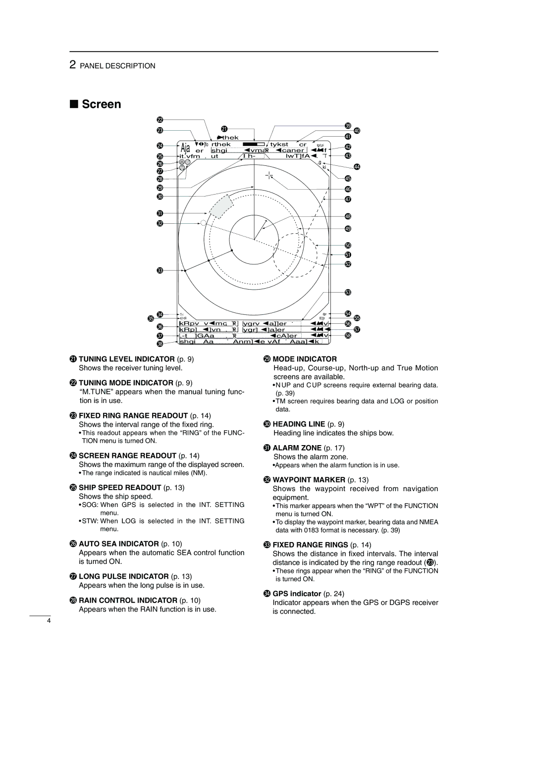
@1TUNING LEVEL INDICATOR (p. 9)
Shows the receiver tuning level.
@2TUNING MODE INDICATOR (p. 9)
“M.TUNE” appears when the manual tuning func- tion is in use.
@3FIXED RING RANGE READOUT (p. 14) Shows the interval range of the fixed ring.
•This readout appears when the “RING” of the FUNC- TION menu is turned ON.
@4SCREEN RANGE READOUT (p. 14)
Shows the maximum range of the displayed screen.
•The range indicated is nautical miles (NM).
@5SHIP SPEED READOUT (p. 13)
Shows the ship speed.
•SOG: When GPS is selected in the INT. SETTING menu.
•STW: When LOG is selected in the INT. SETTING menu.
@9MODE INDICATOR
•N UP and C UP screens require external bearing data. (p. 39)
•TM screen requires bearing data and LOG or position data.
#0HEADING LINE (p. 9)
Heading line indicates the ships bow.
#1ALARM ZONE (p. 17)
Shows the alarm zone.
•Appears when the alarm function is in use.
#2WAYPOINT MARKER (p. 13)
Shows the waypoint received from navigation equipment.
•This marker appears when the “WPT” of the FUNCTION menu is turned ON.
•To display the waypoint marker, bearing data and NMEA data with 0183 format is necessary. (p. 39)
@6AUTO SEA INDICATOR (p. 10)
Appears when the automatic SEA control function is turned ON.
@7LONG PULSE INDICATOR (p. 13) Appears when the long pulse is in use.
@8RAIN CONTROL INDICATOR (p. 10) Appears when the RAIN function is in use.
#3FIXED RANGE RINGS (p. 14)
Shows the distance in fixed intervals. The interval distance is indicated by the ring range readout (@3).
•These rings appear when the “RING” of the FUNCTION is turned ON.
#4GPS indicator (p. 24)
Indicator appears when the GPS or DGPS receiver is connected.
4
