9 INSTALLATION AND CONNECTIONS
■Mounting the EX-2714 scanner unit
WARNING: BE SURE [POWER] is OFF when- ever you are working with the scanner unit.
The scanner unit is designed to be weatherproof and completely watertight. Select a place for installation which meets the following important conditions.
qThe scanner unit must be near the boat’s center line and have a good view in every direction. Be sure there are no objects in the surrounding area which will intercept the scanning beam.
wKEEP the scanner unit away from any smoke- stacks. Smoke can damage the unit.
eWhen the boat is equipped with a radio directional finder (RDF) system, keep the scanner unit at least 2 m (6.6 ft) away from any RDF antenna.
•Radiation from the scanner unit can affect the measure- ment data of RDF equipment.
rThe unit should be placed as high as possible on the boat to obtain best performance with maximum range.
tIf you install two or more radar in one boat, install one above, and one below.
yThe mounting surface must be parallel with the boat’s waterline.
uIf the height is insufficient to install the scanner unit, build a special frame for installation.
DMounting
qDrill four holes of 12 mm (1⁄2 in) in diameter using the template.
wIf the mounting surface or platform is metal, apply sealing compound around the holes to prevent cor- rosion and to waterproof the unit.
eFix the scanner unit to the selected position with bolts of 10 mm (3⁄8 in) in diameter, with flat and spring washers. The supplied bolts are two lengths: 25 mm (1 in) or 50 mm (2 in).
CAUTION: SECURE the four bolts tightly.
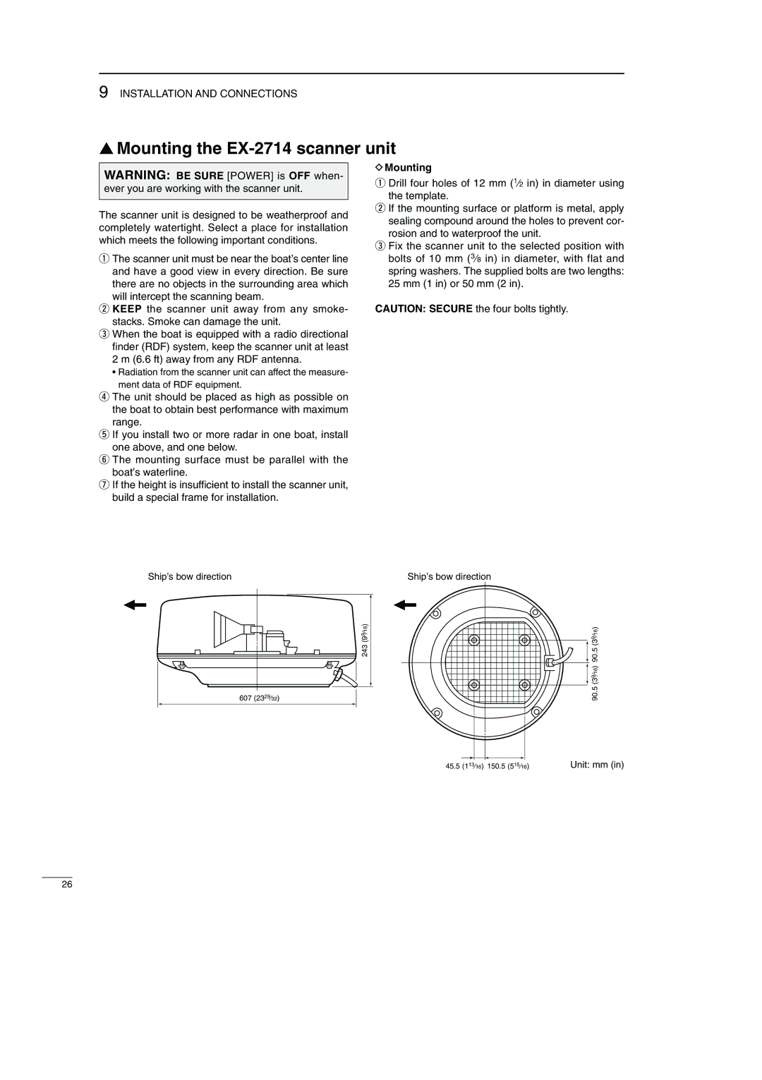
Ship’s bow direction | Ship’s bow direction |
243 (99⁄16)
607 (2329⁄32)
90.5 (39⁄16) 90.5 (39⁄16)
45.5 (113⁄16) 150.5 (515⁄16) | Unit: mm (in) |
26