■TIMING adjustment
The system cable length affects the sweep timing. When the cable length adjustment is not correct, a straight target is shown as a curved echo. Thus, cable length adjustment is necessary.
qPosition your boat near a straight target such as breakwater, wharf, etc.
wPush ![]()
![]()
![]() ] several times to select 1⁄8 or 1⁄4 NM range.
] several times to select 1⁄8 or 1⁄4 NM range.
SERVICE MAN MENU 11
ePush [TX (SAVE)]/[ ![]()
![]()
![]()
![]() ] to display the target on the screen.
] to display the target on the screen.
rPush [MENU]/[ ![]()
![]() ], [Ú] and [≈] several times to display the “SERVICE MAN” menu.
], [Ú] and [≈] several times to display the “SERVICE MAN” menu.
tPush [Ú] until the “TIMING ADJ.” section becomes highlighted.
yPush [Ω ≈] to adjust the echo until it becomes straight. (see below)
u Push [MENU]/[ ![]()
![]() ] to return to the normal screen.
] to return to the normal screen.
Proper adjustment | Improper, pulling inward | Improper, pushing outward |
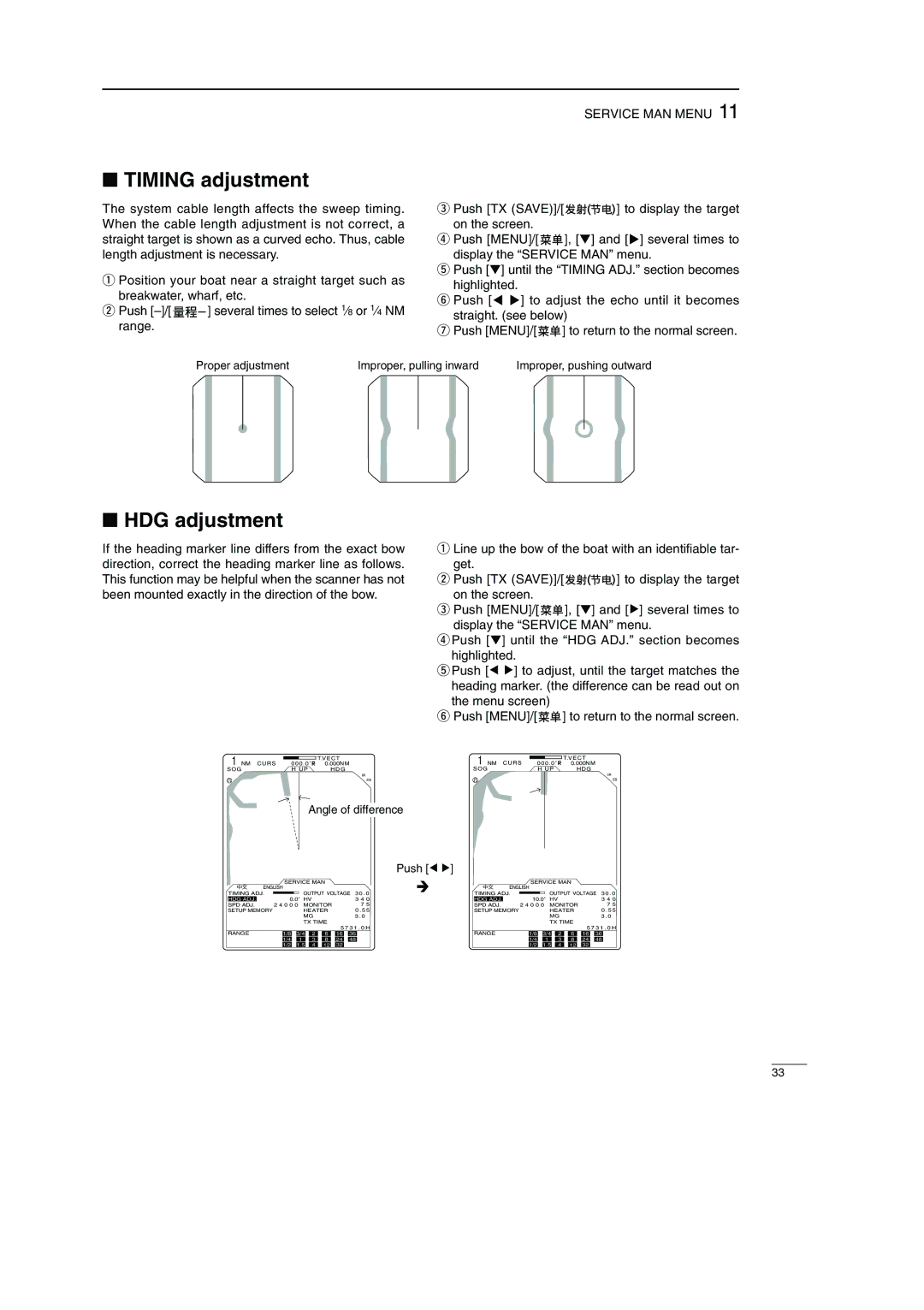
■HDG adjustment
If the heading marker line differs from the exact bow direction, correct the heading marker line as follows. This function may be helpful when the scanner has not been mounted exactly in the direction of the bow.
1![]()
![]() T.V E C T
T.V E C T
NM C U R S 000 . 0 ˚ R 0.000N M
S O G | H UP | HDG |
IR
ES
Angle of difference
qLine up the bow of the boat with an identifiable tar- get.
wPush [TX (SAVE)]/[ ![]()
![]()
![]()
![]() ] to display the target on the screen.
] to display the target on the screen.
ePush [MENU]/[ ![]()
![]() ], [Ú] and [≈] several times to display the “SERVICE MAN” menu.
], [Ú] and [≈] several times to display the “SERVICE MAN” menu.
rPush [Ú] until the “HDG ADJ.” section becomes highlighted.
tPush [Ω ≈] to adjust, until the target matches the heading marker. (the difference can be read out on the menu screen)
yPush [MENU]/[ ![]()
![]() ] to return to the normal screen.
] to return to the normal screen.
1![]()
![]() T.VECT
T.VECT
NM CURS 000 . 0 ˚ R 0.000NM
SOG | H UP | HDG |
IR
ES
Push [Ω ≈]
|
|
| SERVICE MAN |
|
|
|
|
|
|
| SERVICE MAN |
|
|
|
| ||||||||||||||||||
| ENGLISH |
|
|
|
|
|
|
|
|
|
|
|
|
|
| ENGLISH |
|
|
|
|
|
|
|
|
|
|
|
|
| ||||
TIMING ADJ. |
|
|
|
|
| OUTPUT VOLTAGE 3 0 . 0 | TIMING ADJ. |
|
|
|
|
| OUTPUT VOLTAGE 3 0 . 0 | ||||||||||||||||||||
| 0.0˚ |
| 10.0˚ | ||||||||||||||||||||||||||||||
HDG ADJ. |
|
| HV |
|
|
|
|
|
| 3 4 0 | HDG ADJ. |
|
| HV |
|
|
|
|
|
| 3 4 0 | ||||||||||||
SPD ADJ. | 2 4 0 0 0 |
| MONITOR |
| 7 5 | SPD ADJ. | 2 4 0 0 0 |
| MONITOR |
| 7 5 | ||||||||||||||||||||||
SETUP MEMORY |
|
|
|
|
| HEATER |
| 0 . 5 5 | SETUP MEMORY |
|
|
|
|
| HEATER |
| 0 . 5 5 | ||||||||||||||||
|
|
|
|
|
|
| MG |
|
|
|
|
| 3 . 0 |
|
|
|
|
|
|
| MG |
|
|
|
|
| 3 . 0 | ||||||
|
|
|
|
|
|
| TX TIME |
|
|
|
|
|
|
|
|
|
|
| TX TIME |
|
|
|
| ||||||||||
RANGE |
|
|
|
|
|
|
|
|
|
|
| 5 7 3 1 . 0 H | RANGE |
|
|
|
|
|
|
|
|
|
|
| 5 7 3 1 . 0 H | ||||||||
| 1/8 |
|
| 3/4 |
| 2 |
| 6 |
| 16 |
| 36 |
|
| 1/8 |
|
| 3/4 |
| 2 |
| 6 |
| 16 |
| 36 |
| ||||||
|
|
|
|
|
|
|
|
|
|
|
|
|
|
|
|
|
|
|
|
|
|
|
|
|
|
|
|
|
|
|
| ||
|
|
| 1/4 |
| 1 |
| 3 |
| 8 |
| 24 | 48 |
|
|
|
| 1/4 |
| 1 |
| 3 |
| 8 |
| 24 | 48 |
| ||||||
|
|
| 1/2 |
| 1.5 |
| 4 |
| 12 |
| 32 |
|
|
|
|
|
| 1/2 |
| 1.5 |
| 4 |
| 12 |
| 32 |
|
|
| ||||
33