8430/8830/8KE4/8KE8 Ethernet I/O Unit User’s Manual
Version 1.0, January
I-8430I-8830 I-8KE4-GI-8KE8-G
8430/8830/8KE4/8KE8
Table of Contents
Download firmware
Updating MiniOS7 image
Chapter 1. Introduction
Ethernet -based Data Acquisition I/O unit
1.1 Features
ASCII-based protocol DCON Protocol
Various SDK provided free
Simultaneous access by a maximum of 6 host PCs
I/O configurable via the Ethernet
Updateable firmware via the RS-232 port
Internet
Dual Bus design to supports i-8K and i-87K series I/O modules
More flexible I/O combination and Compact、fasten、quick to install
Ventilated housing design to work between -25 ~+75
High performance integrated power supply
Built-in Watchdog
Input Protection circuitry
SRAM
1.2 i-8430/i-8830 Hardware Specifications
EEPROM
Ethernet port
Mounting mechanism
Power supply 20W
Dimension
Real time clock
1.3 i-8KE4/i-8KE8 Hardware Specifications
NVRAM
Mounting mechanism
8430
1.4 Front view of 8430/8830
8830
RS-232/485 COM3
Pin assignment of COM1 Port Pin assignment of COM3 Port
8KE8
1.5 Front view of 8KE4/8KE8
8KE4
Pin assignment of COM1 Port
Method b DIN-Rail mounting Frame Ground DIN-Rail Clips
1.6 8430/8830/8KE4/8KE8 installation
The diagrams below show the basic wiring for the Ethernet I/O
Step2 Attach power supply 10 ~ 30 VDC
22222
11111
44444
33333
For I-87K series modules the files are located at
1.7 I/O module installation
For I-8000 series modules the files are located at
Pin assignment
Wire Connection
Step2 Connect the wire Step3 Insert the I/O module into the 8KE4/8KE8
2.1 Configure the network settings
Chapter 2. Configure the 8430/8830/8KE4/8KE8 and I/O modules
2.1.1 By “Configuration Wizard”
By “Configuration Wizard“ By “MiniOS7 Utility” By “SMMI Menu”
4.1 4.2 4.21
2.1.2 By MiniOS7 Utility
POWER
2.1.3 By SMMI Menu Network Configuration
MODE
DOWN
Following is the SMMI menu tree Cursor position
Step2 The SMMI menu tree
Step3 Selection items that can be changed
DCON Utility
2.3 Configure I/O modules
2.2 Creating a virtual COM port to map the I/O modules
3.1 4.1 4.2 4.3
8430/8830/8KE4/8KE8 User’s manual, Jan 2005, Version 1.0, 8MS-002-10
3.1 The feature of using DCON Protocol
Chapter 3. Using the DCON Protocol
Step 2. Send command with cr
3.2 Using the TCP protocol directly
Step 1. Connect to the Ethernet controller
Step 3. Receive data from Ethernet controller
The result will be as below
3.3 Via VxComm technology
4.1 Location of documents and software
Chapter 4. Software Development ToolKit free
The diagram below show the architecture of the SDK
DCON Utility DOS
4.2.1 Procedure for using the DCON Utility DOS
4.2 DCON Utility DOS
DCON Utility DOS version
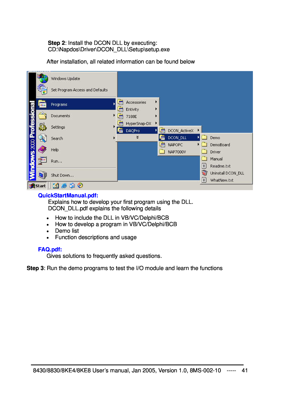
4.3 DCON DLL
4.3.1 Procedure for using the DLL
DLL library
DCON DLL
QuickStartManual.pdf
FAQ.pdf
4.3.2 VB Example Reading an analog input value
Step 7 Write the program code
VB Step VB Step VB Step
Step 8 Run the project
DCON ActiveX
4.4.1 Procedure for using the ActiveX
4.4 DCON ActiveX
ActiveX ocx component Supported modules
4.4.2 VB Example Reading an analog input value
InstallOCX.pdf
Step 5 Add the ActiveX ocx component to the project
Step 7 Write the program code
Step 6 Arrange all the components on the form
VB Step VB Step VB Step
8430/8830/8KE4/8KE8 User’s manual, Jan 2005, Version 1.0, 8MS-002-10
8430/8830/8KE4/8KE8 User’s manual, Jan 2005, Version 1.0, 8MS-002-10
4.5 DCON LabVIEW
4.5.1 Procedure for using DCONLabVIEW
Bundled driver for LabVIEW
DCON LabVIEW
8000Demo Demo programs for I-8000 I/O modules
CallDLLinLabVIEW.pdf Explains how to call a sub-vi of in LabVIEW
8000.llb LabVIEW library contains all sub-vi for I-8000 I/O modules
DCONDLL.pdf Descriptions of all sub-function in DCONDLL
Step3 Select the sub-vi form Functions Palette Select a VI…
Step5 Select the desired sub-vi
4.5.2 LabVIEW Example Reading multi-channel analog Input value
Step4 Select the target *.lib file LabVIEW library file
Step7 Draw the data flow of sub-vi
4.5.2 LabVIEW Demo Program Reading multi-channel analog input value
Step3 Run the demo
2.1 2.2
Step2 Set the parameters
4.6 DCON Indusoft
4.6.1 Procedure for using the Indusoft bundled driver
4.6.2 Indusoft Example Reading an analog input value
DCON Indusoft
Step 5 Include the DCON driver
5.1 5.2 5.3 5.4
Step 4 Run Indusoft and create a new project
Step 6 Configure the DCON driver
Step7 Insert tags to connect to I/O modules
7.1 7.2
The address format is Address ModuleID Slot Channel
Step8 Arrange all the components on the form
Step10 Run the project
9.1 9.2
Step9 Double click the text box to assign a tag to it
4.7.1 Introduction
4.7 NAP OPC Server
NAP OPC server
OPC Server
4.7.2 Procedure for using the OPC server
4.7.3 OPC Server Example Reading an analog input value
Step 4 Run the OPC server to search for I/O modules on COM3
4.1 4.2 4.4 4.3
Step 6 Run SCADA software to connect to the OPC Server
Labview National WIZCON iFix Indusoft Citect
Step 5 Save the configuration and close the OPC Server
i-8430
Appendix A Dimensions
Back View
Top View
Back View
i-8830
Side View
Top View
i-8KE4
i-8KE8
Basic Command Format
Appendix B DCON protocol
Frequently used Command table reference
B.1 Command Set
+2.1234+2.1234 +2.1234 +2.1234 cr
#01S3
+2.1234+2.1234 +2.1234 +2.1234
Command
+2.1234cr
#01S3C0
#01S3C1-05.000
#01S3C1+09.000
$AASi6
A Command to read the data
Read back the Digital Output module value and read the Digital Input
module value of a specified slot in the I-8000 unit
#01S300AA55cr
#01S30042
8430/8830/8KE4/8KE8 User’s manual, Jan 2005, Version 1.0, 8MS-002-10
#01S31A00cr
#01S31C01
#01S31000
Channel Status
Set the Channel 0 DO OFF
#01S31001
B.2 Hardware interface
Use Virtual COM Port interface
Appendix C VxComm technique
The two application architectures are shown as below
Appendix D i-8K and i-87K series I/O modules
i-87K series
i-8000 series
Appendix E Updating firmware and MiniOS7 image
CA-0915
E.1 Access the controller
Power 10~ 30 VDC
Step5 Run MiniOS7 Utility Step6 Select the COM port of the host PC
6.1 6.2
ii. Files in the Flash ROM
2. List files in the Flash ROM 1. MiniOS7 image information
i. MiniOS7 image version of the 8430/8830/8KE4/8KE8
E.2 Updating MiniOS7 image
E.3 Download firmware