Section 2

INSTALLATION

Host Connections

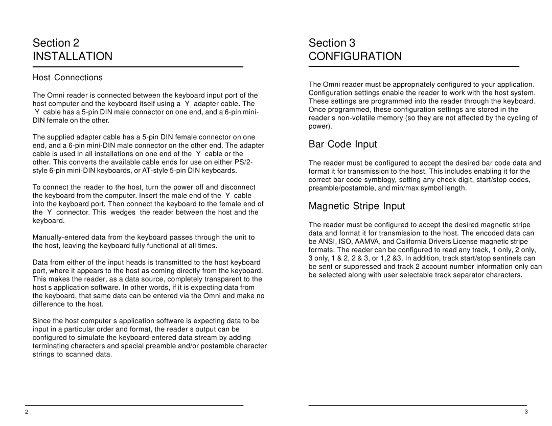
The Omni reader is connected between the keyboard input port of the host computer and the keyboard itself using a “Y” adapter cable. The “Y” cable has a 5-pin DIN male connector on one end, and a 6-pin mini- DIN female on the other.

The supplied adapter cable has a 5-pin DIN female connector on one end, and a 6-pin mini-DIN male connector on the other end. The adapter cable is used in all installations on one end of the “Y” cable or the other. This converts the available cable ends for use on either PS/2- style 6-pin mini-DIN keyboards, or AT-style 5-pin DIN keyboards.

To connect the reader to the host, turn the power off and disconnect the keyboard from the computer. Insert the male end of the “Y” cable into the keyboard port. Then connect the keyboard to the female end of the “Y” connector. This “wedges” the reader between the host and the keyboard.

Manually-entered data from the keyboard passes through the unit to the host, leaving the keyboard fully functional at all times.

Data from either of the input heads is transmitted to the host keyboard port, where it appears to the host as coming directly from the keyboard. This makes the reader, as a data source, completely transparent to the host’s application software. In other words, if it is expecting data from the keyboard, that same data can be entered via the Omni and make no difference to the host.

Since the host computer’s application software is expecting data to be input in a particular order and format, the reader’s output can be configured to simulate the keyboard-entered data stream by adding terminating characters and special preamble and/or postamble character strings to scanned data.

Section 3

CONFIGURATION

The Omni reader must be appropriately configured to your application. Configuration settings enable the reader to work with the host system. These settings are programmed into the reader through the keyboard.

Once programmed, these configuration settings are stored in the reader’s non-volatile memory (so they are not affected by the cycling of power).

Bar Code Input

The reader must be configured to accept the desired bar code data and format it for transmission to the host. This includes enabling it for the correct bar code symblogy, setting any check digit, start/stop codes, preamble/postamble, and min/max symbol length.

Magnetic Stripe Input

The reader must be configured to accept the desired magnetic stripe data and format it for transmission to the host. The encoded data can be ANSI, ISO, AAMVA, and California Drivers License magnetic stripe formats. The reader can be configured to read any track, 1 only, 2 only,

3 only, 1 & 2, 2 & 3, or 1,2 &3. In addition, track start/stop sentinels can be sent or suppressed and track 2 account number information only can be selected along with user selectable track separator characters.

2

3

Page 4
Image 4
ID Tech 80, 25, 60, 50, 30, 70 user manual Installation, Configuration, Bar Code Input, Magnetic Stripe Input, Host Connections

30, 70, 60, 80, 50 specifications

ID Tech is a leading provider of payment solutions, and their ID Tech 70, 30, 50, 25, and 60 series terminals represent the forefront of mobile and secure payment technology. Each model in this series is designed with unique features catering to various business needs, ensuring that payment processing remains seamless and efficient.

The ID Tech 70 is characterized by its robust construction and reliability, making it suitable for both retail and hospitality sectors. It supports various payment methods, including magnetic stripe, EMV chip cards, and contactless payments, ensuring a versatile solution for modern businesses. One of its standout features is the dual interface, which allows for quick transactions while enhancing security through encryption technologies.

Moving to the ID Tech 30, this model is known for its compact design and portability, making it an excellent choice for businesses on the go. Its lightweight nature does not compromise functionality, as it supports all traditional forms of payment along with NFC-enabled transactions. The integration capabilities of the ID Tech 30 are impressive, allowing businesses to easily connect to existing POS systems or mobile devices.

The ID Tech 50 is designed for a more demanding environment, with an emphasis on durability and advanced security features. It includes advanced encryption and tokenization to protect sensitive cardholder information during transactions. Additionally, its large display screen improves user interaction, and its ergonomic design ensures comfort during prolonged usage.

The ID Tech 25 is an entry-level model that offers essential functionalities at an affordable price point. It supports magnetic stripe and EMV payments, making it a solid choice for small businesses looking to upgrade their payment systems without overspending. The ID Tech 25’s simplicity allows for quick setup and ease of use, which is ideal for businesses new to digital payments.

Finally, the ID Tech 60 is a premium solution featuring advanced payment technology coupled with a larger interface for showcasing promotional content. It supports multi-currency transactions, making it perfect for businesses with international customers. Its enhanced security measures ensure protection against fraud, while the integration of loyalty programs adds further value to the customer experience.

In summary, the ID Tech series, with its 70, 30, 50, 25, and 60 models, offers a comprehensive range of payment solutions tailored to various business needs. Each terminal provides unique features and cutting-edge technologies, ensuring secure and efficient payment processing suitable for any environment. With ongoing innovations in payment technology, ID Tech remains a trusted choice for businesses aiming to stay ahead in the digital payment landscape.