Appendix B | |
|
|
Table B1.3
Connector | Description |
|
|
J9, J10 | Primary IDE (Master / Slave) |
J9a, J10a | Primary IDE (Master / Slave) |
|
|
J11 | COM1, Mouse & Keyboard |
J13 | LPT1 & COM2 |
|
|
J13a | LPT1 & COM2* |
|
|
B1.4 ICP-HDE8MS (Theme Variation)
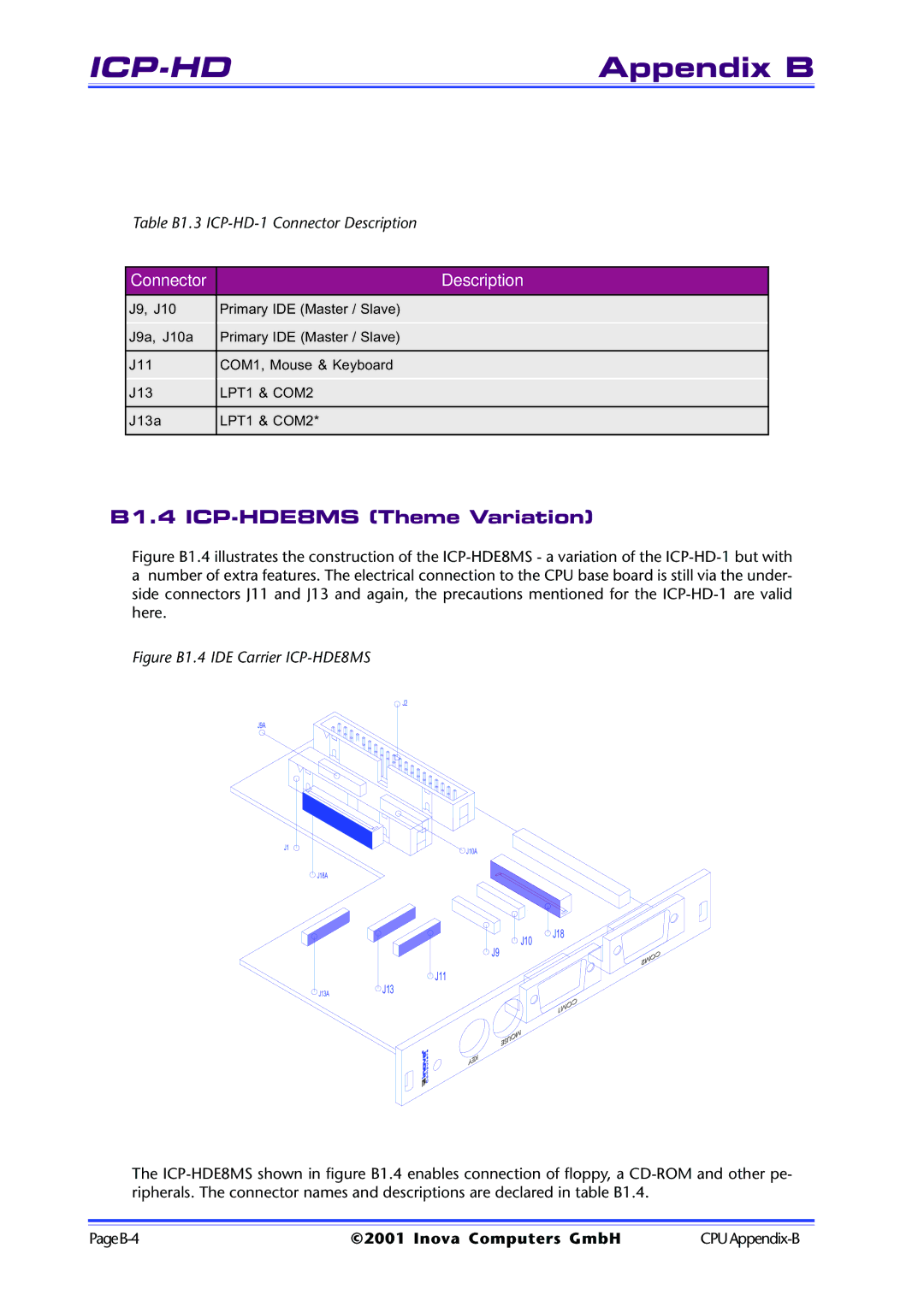
Figure B1.4 illustrates the construction of the ICP-HDE8MS - a variation of the ICP-HD-1 but with
anumber of extra features. The electrical connection to the CPU base board is still via the under- side connectors J11 and J13 and again, the precautions mentioned for the ICP-HD-1 are valid here.
Figure B1.4 IDE Carrier ICP-HDE8MS
J2
J9A
J1 | J10A |
| |
| J18A |
J10
J9
J11
J13AJ13
J18
The
©2001 Inova Computers GmbH |