B1.8 COM1 & COM 2 Interfaces
The two COM ports feature a complete set of handshaking and modem control signals, maskable interrupt generation and high-speed data transfer rates. A front-panel with COM1, COM2, mouse and keyboard interfaces is either integrated into an 8HP standard CPU front-panel or available as a separate 4HP unit. The IDE carrier board located behind these interfaces connects to the CPU- mounted J11 and J13 connectors.
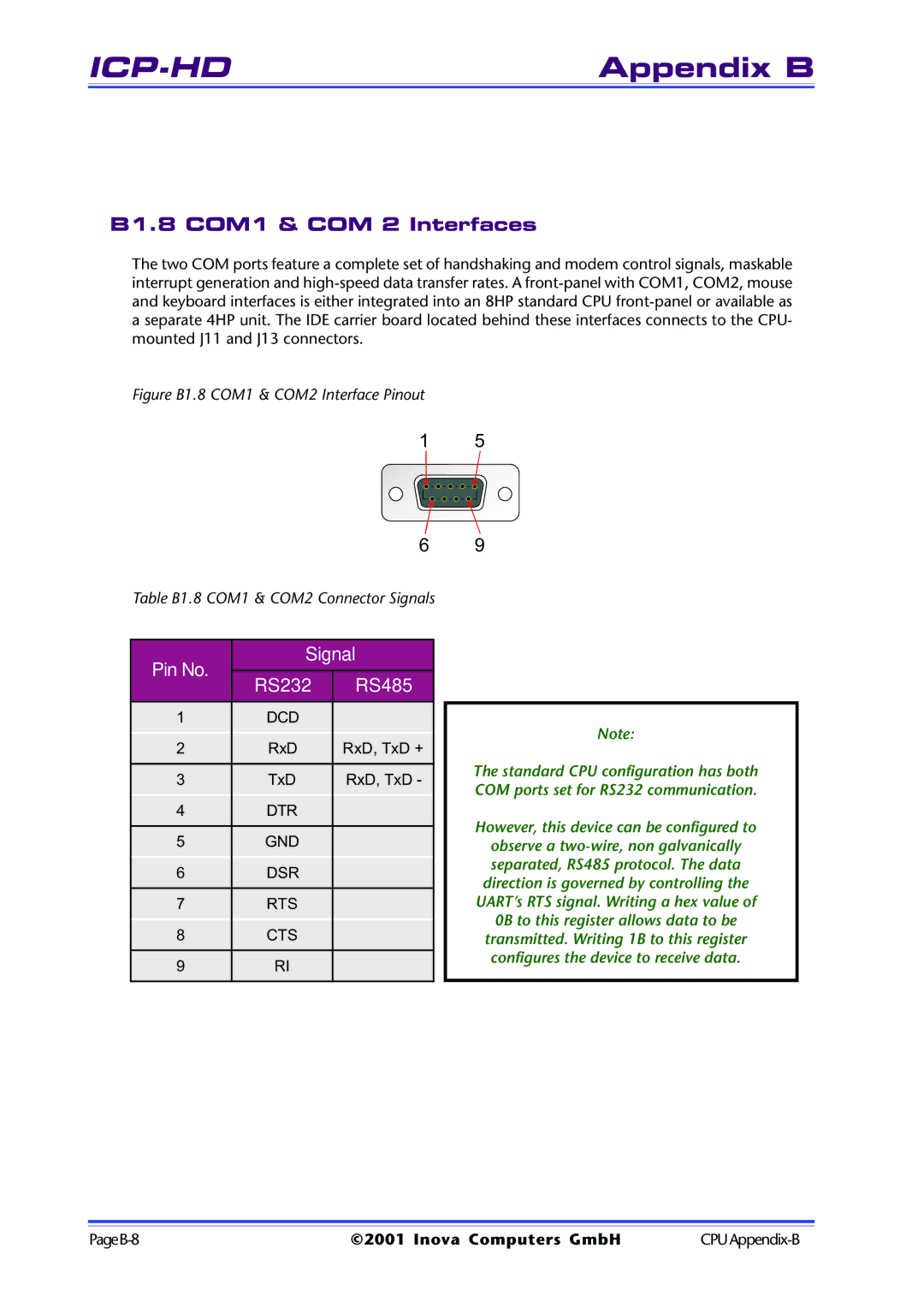
Figure B1.8 COM1 & COM2 Interface Pinout
15
6 9
Table B1.8 COM1 & COM2 Connector Signals
| Pin No. | Signal |
| | |
| RS232 | RS485 |
| |
| | | |
| 1 | DCD | |
| 2 | RxD | RxD, TxD + |
| | | |
| 3 | TxD | RxD, TxD - |
| 4 | DTR | |
| | | |
| 5 | GND | |
| 6 | DSR | |
| | | |
| 7 | RTS | |
| 8 | CTS | |
| | | |
| 9 | RI | |
| | | |
Note:
The standard CPU configuration has both COM ports set for RS232 communication.
However, this device can be configured to
observe a two-wire, non galvanically separated, RS485 protocol. The data direction is governed by controlling the UART’s RTS signal. Writing a hex value of 0B to this register allows data to be transmitted. Writing 1B to this register configures the device to receive data.
PageB-8 | ©2001 Inova Computers GmbH | CPUAppendix-B |