Appendix C | |
|
|
®CompactPCI
C1.3 LPT1 & COM2 Piggyback
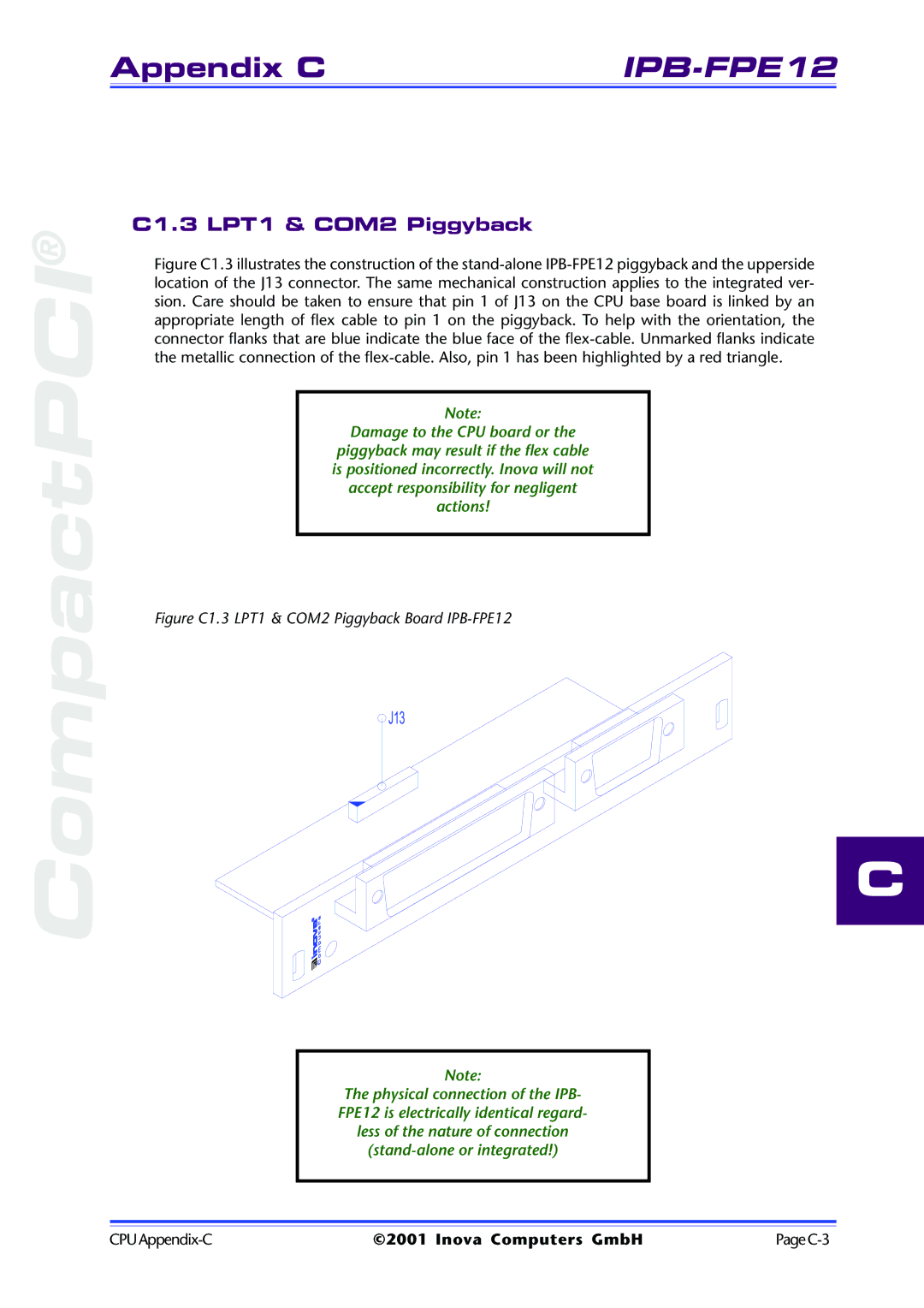
Figure C1.3 illustrates the construction of the stand-alone IPB-FPE12 piggyback and the upperside location of the J13 connector. The same mechanical construction applies to the integrated ver- sion. Care should be taken to ensure that pin 1 of J13 on the CPU base board is linked by an appropriate length of flex cable to pin 1 on the piggyback. To help with the orientation, the connector flanks that are blue indicate the blue face of the flex-cable. Unmarked flanks indicate the metallic connection of the flex-cable. Also, pin 1 has been highlighted by a red triangle.
Note:
Damage to the CPU board or the
piggyback may result if the flex cable is positioned incorrectly. Inova will not accept responsibility for negligent actions!
Figure C1.3 LPT1 & COM2 Piggyback Board IPB-FPE12
J13
C
Note:
The physical connection of the IPB- FPE12 is electrically identical regard- less of the nature of connection
©2001 Inova Computers GmbH |