Appendix A | |
|
|
A1.4 IPB-FPE8MS (Theme Variation)
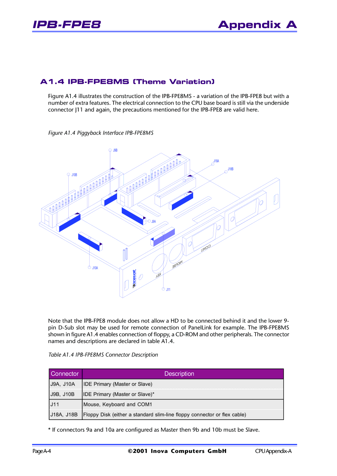
Figure A1.4 illustrates the construction of the IPB-FPE8MS - a variation of the IPB-FPE8 but with a number of extra features. The electrical connection to the CPU base board is still via the underside connector J11 and again, the precautions mentioned for the IPB-FPE8 are valid here.
Figure A1.4 Piggyback Interface IPB-FPE8MS
J9B
J18A
J18B
J10B
J9A
J10A
J11
Note that the
Table A1.4
Connector | Description |
|
|
J9A, J10A | IDE Primary (Master or Slave) |
J9B, J10B | IDE Primary (Master or Slave)* |
|
|
J11 | Mouse, Keyboard and COM1 |
J18A, J18B | Floppy Disk (either a standard |
|
|
* If connectors 9a and 10a are configured as Master then 9b and 10b must be Slave.
©2001 Inova Computers GmbH |