®CompactPCI

ICP-PIIIInterfaces

3.22 J17 VGA Interface

J17 is available on the CPU front-panel if this option is required and if this position is not already occupied by a PCI, PanelLink or GigaST)R piggyback. The 15-pin high-density D-Sub connector forms the physical interface for the video on the ICP-PIII which is based on either the Silicon Motion Lynx3DM graphic accelerator equipped with 8MByte RAM or the Radeon VE controller with 16MByte RAM. In both cases, the controller is a highly integrated 128-bit GUI (Grahpical User Interface) engine that has been optimized for handling graphic-intensive environments like those found in Windows NT.

The controller uses a 64-bit data path to the RAM video memory, a 24-bit high-performance 135

3

MHz RAMDAC and a flat-panel interface capable of controlling the latest STN and TFT panels.

All ICP-PIII CPUs, if prepared for graphics, are equipped with 8/16MByte high-speed RAM sup- porting resolutions up to 1600 x 1200 pixels with 24-bit (True Colour) depth or 2048 x 1536 pixels with 16-bit (Hi-Colour) depth. VGA, SVGA, XGA, XSGA Composite video and TFT dual- scan/single-scan colour panels are supported with configurable colour depths.

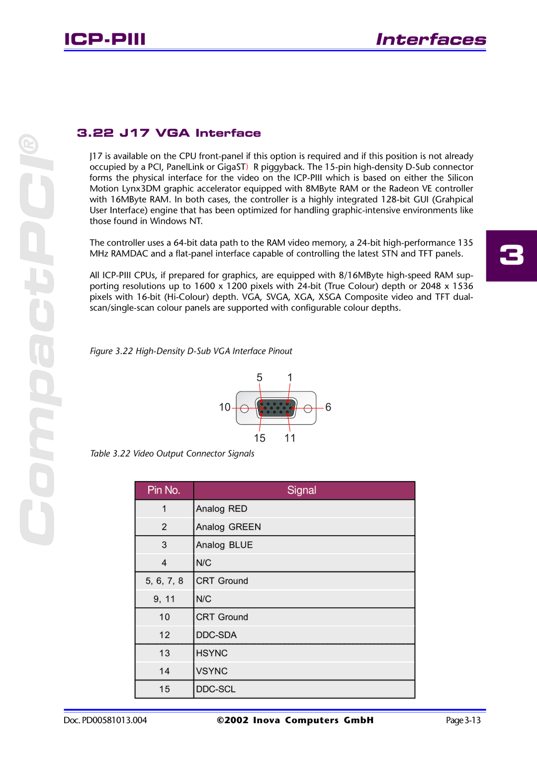
Figure 3.22 High-Density D-Sub VGA Interface Pinout

51

10 6

15 11

Table 3.22 Video Output Connector Signals


Pin No.

Signal


1

Analog RED


2

Analog GREEN


3

Analog BLUE


4

N/C


5, 6, 7, 8

CRT Ground


9, 11

N/C


10

CRT Ground


12

DDC-SDA


13

HSYNC


14

VSYNC


15

DDC-SCL


Doc. PD00581013.004

©2002 Inova Computers GmbH

Page3-13

Page 47
Image 47
Inova ICP-PII user manual 22 J17 VGA Interface