DTR-7.1 specifications
The Integra DTR-7.1 is a distinguished A/V receiver that exemplifies high-performance audio and video processing for home theater enthusiasts. Known for its meticulous engineering and robust feature set, the DTR-7.1 appeals to both audiophiles and casual viewers alike.At the heart of the Integra DTR-7.1 lies a powerful amplification system that delivers 7.1 channels of immersive surround sound. With a substantial power output, the receiver ensures that even the most demanding soundtracks are reproduced with accuracy and clarity. The discrete power amplifier design contributes to lower distortion levels, providing a cleaner audio experience.
One of the standout features of the Integra DTR-7.1 is its advanced audio processing capabilities. It supports several high-definition formats, including Dolby TrueHD and DTS-HD Master Audio. This wide array of decoding options allows for a richly detailed auditory experience, especially when paired with high-definition media.
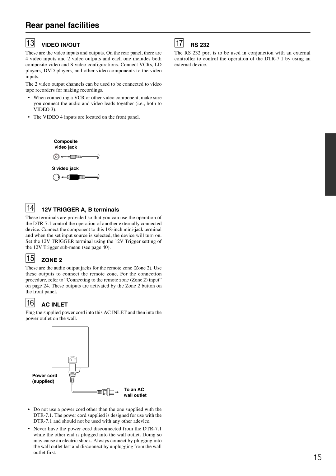
Moreover, the DTR-7.1 is equipped with cutting-edge video processing technology. It supports 4K and 1080p video resolutions, ensuring compatibility with the latest video formats. The integrated video scaling feature upscales lower-resolution content to near-4K quality, enhancing the viewing experience regardless of the source material.
Connectivity is another strong suit of the Integra DTR-7.1. The receiver boasts multiple HDMI inputs, facilitating easy connection to various devices such as Blu-ray players, gaming consoles, and streaming devices. Additionally, it supports features like ARC (Audio Return Channel) and CEC (Consumer Electronics Control), streamlining control and simplifying the setup process.
For ultimate customization, the DTR-7.1 includes an advanced auto-calibration system, which optimally adjusts sound settings based on the acoustics of the room and the speaker placement. This technology ensures that users achieve the best possible sound regardless of their home theater setup.
Finally, the Integra DTR-7.1 offers comprehensive network capabilities. It supports streaming services and internet radio, providing users with access to a vast library of music and content. Integration with home automation systems is also seamless, allowing users to control the receiver through smart devices for added convenience.
In summary, the Integra DTR-7.1 stands out as a top-tier A/V receiver, combining superior amplification, advanced audio and video processing, extensive connectivity options, and smart features, making it a worthy addition to any home theater system.

