Thermal Metrology
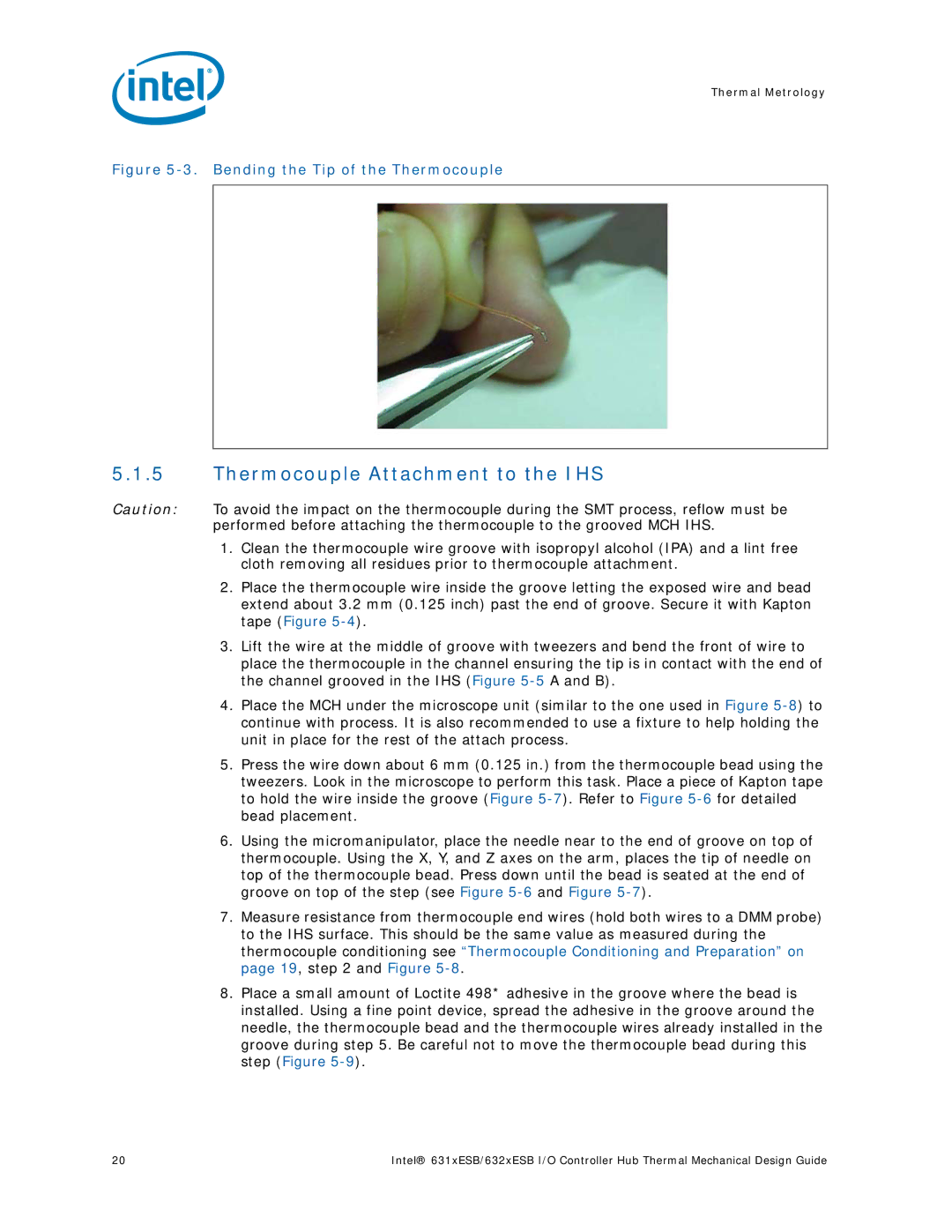
Figure 5-3. Bending the Tip of the Thermocouple
5.1.5Thermocouple Attachment to the IHS
Caution: To avoid the impact on the thermocouple during the SMT process, reflow must be performed before attaching the thermocouple to the grooved MCH IHS.
1.Clean the thermocouple wire groove with isopropyl alcohol (IPA) and a lint free cloth removing all residues prior to thermocouple attachment.
2.Place the thermocouple wire inside the groove letting the exposed wire and bead extend about 3.2 mm (0.125 inch) past the end of groove. Secure it with Kapton tape (Figure
3.Lift the wire at the middle of groove with tweezers and bend the front of wire to place the thermocouple in the channel ensuring the tip is in contact with the end of the channel grooved in the IHS (Figure
4.Place the MCH under the microscope unit (similar to the one used in Figure
5.Press the wire down about 6 mm (0.125 in.) from the thermocouple bead using the tweezers. Look in the microscope to perform this task. Place a piece of Kapton tape to hold the wire inside the groove (Figure
6.Using the micromanipulator, place the needle near to the end of groove on top of thermocouple. Using the X, Y, and Z axes on the arm, places the tip of needle on top of the thermocouple bead. Press down until the bead is seated at the end of groove on top of the step (see Figure
7.Measure resistance from thermocouple end wires (hold both wires to a DMM probe) to the IHS surface. This should be the same value as measured during the thermocouple conditioning see “Thermocouple Conditioning and Preparation” on page 19, step 2 and Figure
8.Place a small amount of Loctite 498* adhesive in the groove where the bead is installed. Using a fine point device, spread the adhesive in the groove around the needle, the thermocouple bead and the thermocouple wires already installed in the groove during step 5. Be careful not to move the thermocouple bead during this step (Figure
20 | Intel® 631xESB/632xESB I/O Controller Hub Thermal Mechanical Design Guide |