Reference Thermal Solution
6.3Mechanical Design Envelope
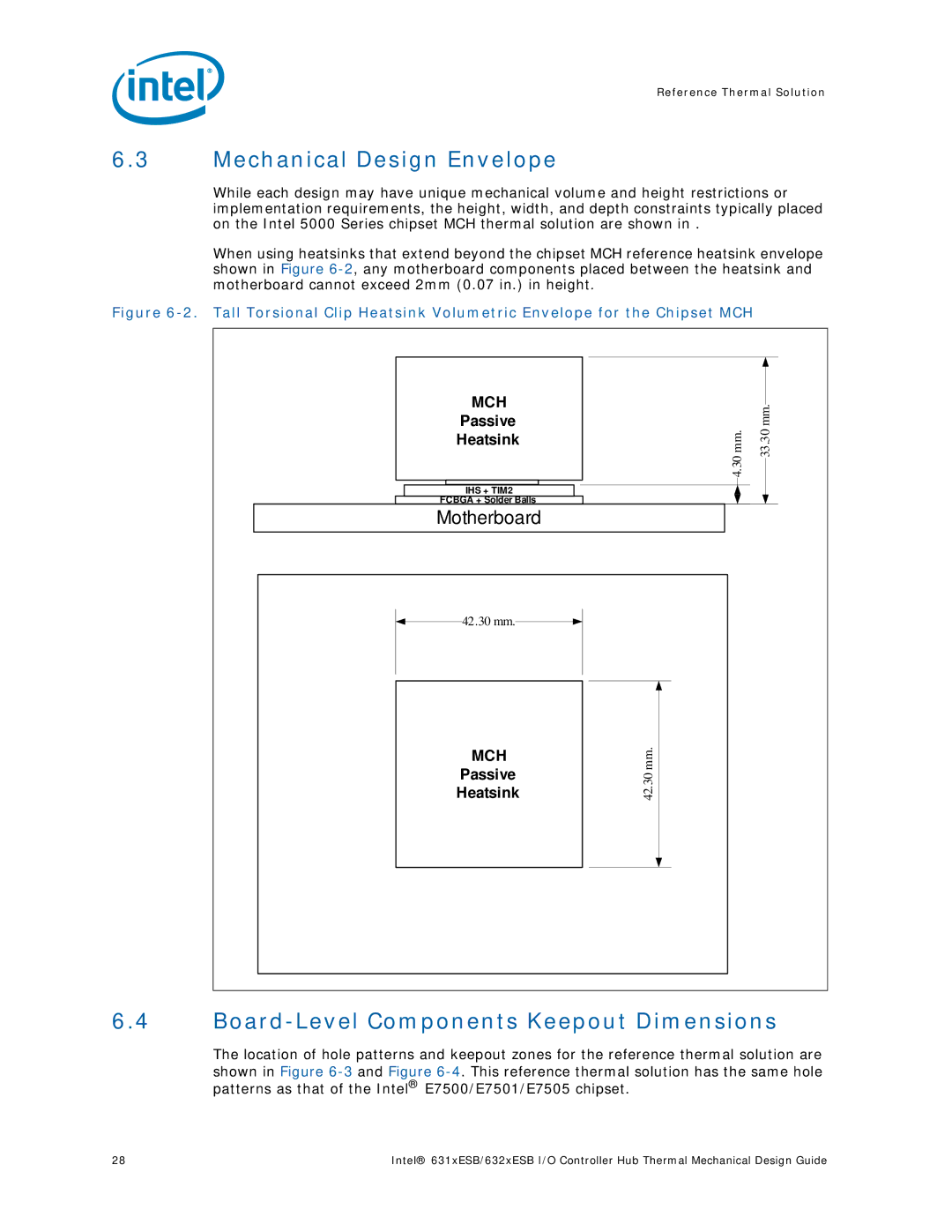
While each design may have unique mechanical volume and height restrictions or implementation requirements, the height, width, and depth constraints typically placed on the Intel 5000 Series chipset MCH thermal solution are shown in .
When using heatsinks that extend beyond the chipset MCH reference heatsink envelope shown in Figure
Figure 6-2. Tall Torsional Clip Heatsink Volumetric Envelope for the Chipset MCH
MCH |
| mm. |
Passive |
| |
Heatsink | 4.30 mm. | 33.30 |
| ||
IHS + TIM2 |
|
|
FCBGA + Solder Balls |
|
|
Motherboard |
|
|
42.30 mm. |
|
|
TNB |
|
|
Heatsink |
|
|
MCH | mm. |
|
Passive |
| |
42.30 |
| |
Heatsink |
|
6.4Board-Level Components Keepout Dimensions
The location of hole patterns and keepout zones for the reference thermal solution are shown in Figure
28 | Intel® 631xESB/632xESB I/O Controller Hub Thermal Mechanical Design Guide |