Thermal Metrology
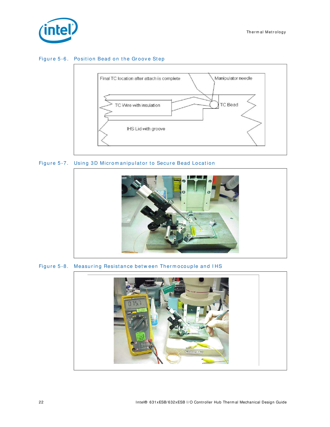
Figure 5-6. Position Bead on the Groove Step
Figure 5-7. Using 3D Micromanipulator to Secure Bead Location
Figure 5-8. Measuring Resistance between Thermocouple and IHS
22 | Intel® 631xESB/632xESB I/O Controller Hub Thermal Mechanical Design Guide |