Reference Thermal Solution 2
Figure 7-4. Retention Mechanism Component Keepout Zones
0.345
0.07" Component
Keepout
| 0.896 |
| 0.120 |
1.156 | 0.170 |
0.070
"
Component
Keepout
2x
0.060
0.225
See Detail
A
(0.345)
0.345
Detail
A
0.165
0.173
(0.165) |
0.083
2x
0.038
Plated Through
Hole
0.200
![]() 0.100
0.100
2x
0.100
Component
Keepout
0.056 Trace Keepout
Note: NOTE: All dimensions are in inches.
7.5.1Heatsink Orientation
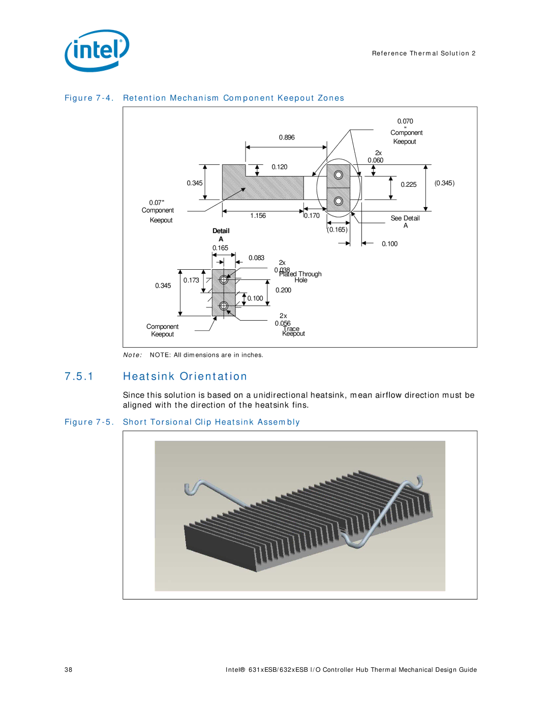
Since this solution is based on a unidirectional heatsink, mean airflow direction must be aligned with the direction of the heatsink fins.
Figure 7-5. Short Torsional Clip Heatsink Assembly
38 | Intel® 631xESB/632xESB I/O Controller Hub Thermal Mechanical Design Guide |