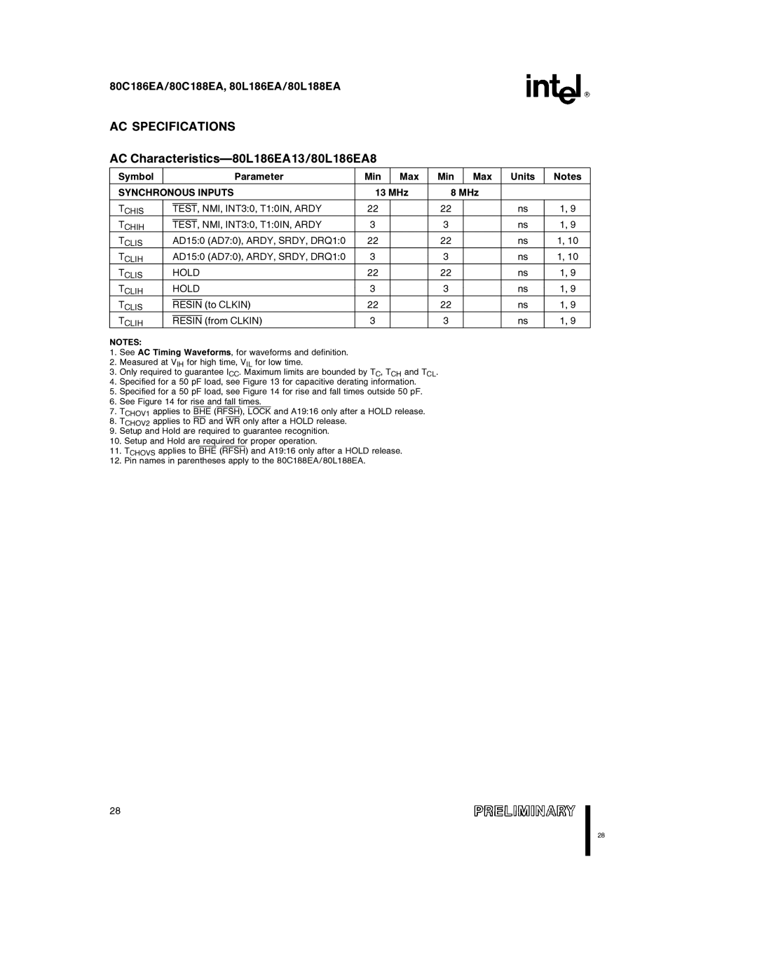
80L186EA, 80L188EA, 80C186EA, 80C188EA specifications
The Intel 80C188EA, 80C186EA, 80L188EA, and 80L186EA microprocessors represent significant developments in the realm of embedded computing during the 1980s. These processors are part of Intel's x86 architecture, designed to cater to a variety of industrial applications, including automotive and telecommunications.The 80C188EA and 80C186EA are CMOS variants that offer enhanced power efficiency and reduced heat generation compared to their NMOS predecessors. Operating at clock speeds of up to 25 MHz, these processors are known for their performance in real-time applications. The 80C188EA features a 16-bit data bus and a 16-bit address bus, which can support up to 1 MB of addressable memory. It also boasts an extended instruction set for greater computing flexibility, making it suitable for intricate tasks in embedded systems.
Similarly, the 80C186EA is characterized by its 16-bit architecture, but it includes additional on-chip memory management capabilities. This processor can handle 256 KB of memory directly and supports paged memory management, facilitating efficient multitasking and resource sharing in complex applications. Its integrated DMA controller and interrupt controller allow for superior handling of peripheral devices, making it ideal for real-time processing requirements.
On the other hand, the 80L188EA and 80L186EA are low-power variants optimized for battery-operated designs. These microprocessors are tailored for applications where power consumption is critical. The 80L188EA retains the essential features of the 80C188EA but operates at lower voltage levels, thus allowing for longer operational life in portable devices. The 80L186EA similarly benefits from reduced power consumption, taking advantage of its energy-efficient design to enhance durability in industrial automation scenarios.
All four processors leverage Intel's established x86 architecture, enabling a wide range of software compatibility. Their built-in support for real-time interrupt handling and I/O operations provides developers with valuable tools for building reliable embedded systems. Additionally, they feature on-chip oscillators and timers, further streamlining design requirements and reducing the need for external components.
Overall, the Intel 80C188EA, 80C186EA, 80L188EA, and 80L186EA processors are ideal for diverse applications in embedded systems. Their blend of processing power, energy efficiency, and versatility continues to influence the design of modern electronic devices, underscoring Intel's pivotal role in advancing microprocessor technology.

