UPI-C42/UPI-L42
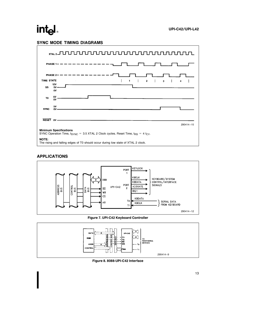
SYNC MODE TIMING DIAGRAMS
290414 – 15
Minimum Specifications
SYNC Operation Time, tSYNC e 3.5 XTAL 2 Clock cycles. Reset Time, tRS e 4 tCY.
NOTE:
The rising and falling edges of T0 should occur during low state of XTAL 2 clock.
APPLICATIONS
290414 – 12
Figure 7. UPI-C42 Keyboard Controller
290414 – 9
Figure 8. 8088-UPI-C42 Interface
13
