UNIVERSAL PERIPHERAL INTERFACE
CHMOS
YPin, Software and Architecturally Compatible with all
YLow Voltage Operation with the UPI- L42
— Full 3.3V Support
YHardware A20 Gate Support
YSuspend Power Down Mode
YSecurity Bit Code Protection Support
Y
Y4096 x 8 ROM/OTP, 256 x 8 RAM
YDMA, Interrupt, or Polled Operation Supported
YOne
YFully Compatible with all Intel and Most Other Microprocessor Families
YInterchangeable ROM and OTP EPROM Versions
YExpandable I/O
YSync Mode Available
YOver 90 Instructions: 70% Single Byte
YQuick Pulse Programming Algorithm
— Fast OTP Programming
YAvailable in
(See Packaging Spec., Order Ý240800, Package Type P, N, and S)
The
The
The
To allow full user flexibility, the program memory is available in ROM and
290414 – 1 |
|
| |
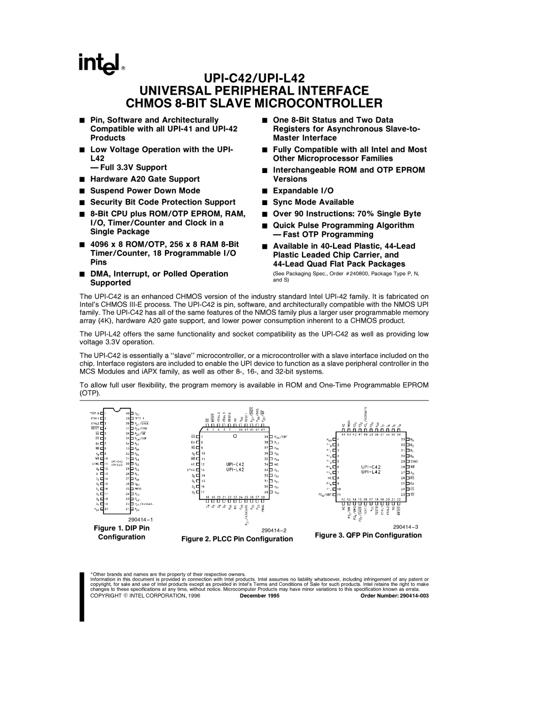
Figure 1. DIP Pin | 290414 – 2 | 290414 – 3 | |
| Figure 3. QFP Pin Configuration | ||
Configuration | Figure 2. PLCC Pin Configuration | ||
| |||
|
|
*Other brands and names are the property of their respective owners.
Information in this document is provided in connection with Intel products. Intel assumes no liability whatsoever, including infringement of any patent or copyright, for sale and use of Intel products except as provided in Intel’s Terms and Conditions of Sale for such products. Intel retains the right to make changes to these specifications at any time, without notice. Microcomputer Products may have minor variations to this specification known as errata.
COPYRIGHT ' INTEL CORPORATION, 1996 | December 1995 | Order Number: |
