UPI-C42/UPI-L42
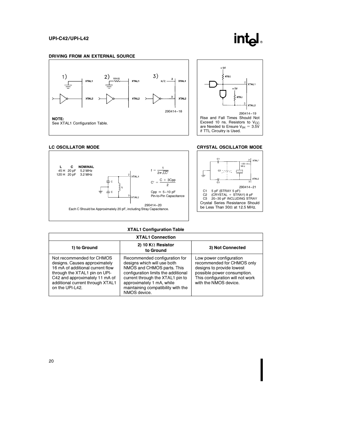
DRIVING FROM AN EXTERNAL SOURCE
NOTE:
See XTAL1 Configuration Table.
290414 – 18
290414 – 19
Rise and Fall Times Should Not Exceed 10 ns. Resistors to VCC are Needed to Ensure VIH e 3.5V if TTL Circuitry is Used.
LC OSCILLATOR MODE | CRYSTAL OSCILLATOR MODE |
L | C | NOMINAL | 1 | |||
45 H | 20 pF | 5.2 MHz | f e |
|
| |
|
| |||||
2q0LC˚ | ||||||
120 H | 20 pF | 3.2 MHz |
| |||
|
|
| ||||
C˚ e C a 3Cpp 2
Cpp j 5 – 10 pF
290414 – 20
Each C Should be Approximately 20 pF, including Stray Capacitance.
290414 – 21
C1 5 pF (STRAY 5 pF)
C2 (CRYSTAL a STRAY) 8 pF
C3 20 – 30 pF INCLUDING STRAY
Crystal Series Resistance Should be Less Than 30X at 12.5 MHz.
XTAL1 Configuration Table
XTAL1 Connection
1) to Ground | 2) 10 KX Resistor | 3) Not Connected | |
to Ground | |||
|
| ||
|
|
| |
Not recommended for CHMOS | Recommended configuration for | Low power configuration | |
designs. Causes approximately | designs which will use both | recommended for CHMOS only | |
16 mA of additional current flow | NMOS and CHMOS parts. This | designs to provide lowest | |
through the XTAL1 pin on UPI- | configuration limits the additional | possible power consumption. | |
C42 and approximately 11 mA of | current through the XTAL1 pin to | This configuration will not work | |
additional current through XTAL1 | approximately 1 mA, while | with the NMOS device. | |
on the | maintaining compatibility with the |
| |
| NMOS device. |
| |
|
|
|
20