UPI-C42/UPI-L42
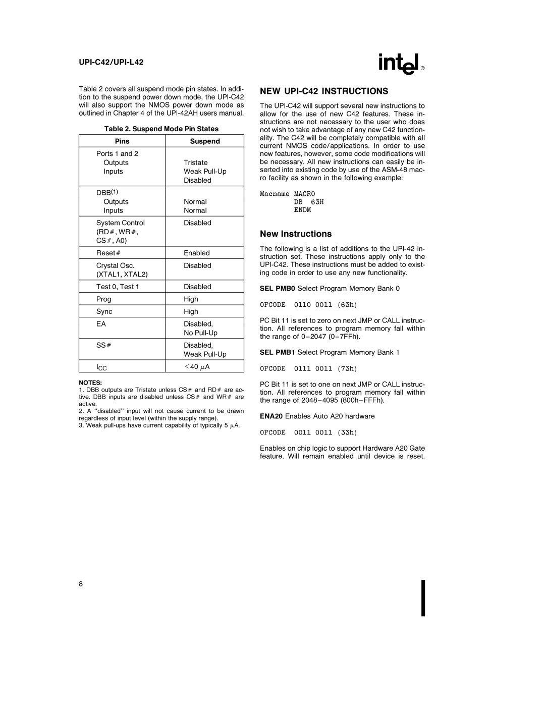
Table 2 covers all suspend mode pin states. In addi- tion to the suspend power down mode, the
Table 2. Suspend Mode Pin States
Pins | Suspend |
|
|
Ports 1 and 2 |
|
Outputs | Tristate |
Inputs | Weak |
| Disabled |
|
|
DBB(1) |
|
Outputs | Normal |
Inputs | Normal |
|
|
System Control | Disabled |
(RDÝ, WRÝ, |
|
CSÝ, A0) |
|
|
|
ResetÝ | Enabled |
|
|
Crystal Osc. | Disabled |
(XTAL1, XTAL2) |
|
|
|
Test 0, Test 1 | Disabled |
|
|
Prog | High |
|
|
Sync | High |
|
|
EA | Disabled, |
| No |
|
|
SSÝ | Disabled, |
| Weak |
|
|
ICC | k40 mA |
NOTES:
1.DBB outputs are Tristate unless CSÝ and RDÝ are ac- tive. DBB inputs are disabled unless CSÝ and WRÝ are active.
2.A ‘‘disabled’’ input will not cause current to be drawn regardless of input level (within the supply range).
3.Weak
NEW UPI-C42 INSTRUCTIONS
The
Macname MACRO
DB 63H
ENDM
New Instructions
The following is a list of additions to the
SEL PMB0 Select Program Memory Bank 0
OPCODE 0110 0011 (63h)
PC Bit 11 is set to zero on next JMP or CALL instruc- tion. All references to program memory fall within the range of 0 – 2047 (0 – 7FFh).
SEL PMB1 Select Program Memory Bank 1
OPCODE 0111 0011 (73h)
PC Bit 11 is set to one on next JMP or CALL instruc- tion. All references to program memory fall within the range of 2048 – 4095 (800h – FFFh).
ENA20 Enables Auto A20 hardware
OPCODE 0011 0011 (33h)
Enables on chip logic to support Hardware A20 Gate feature. Will remain enabled until device is reset.
8