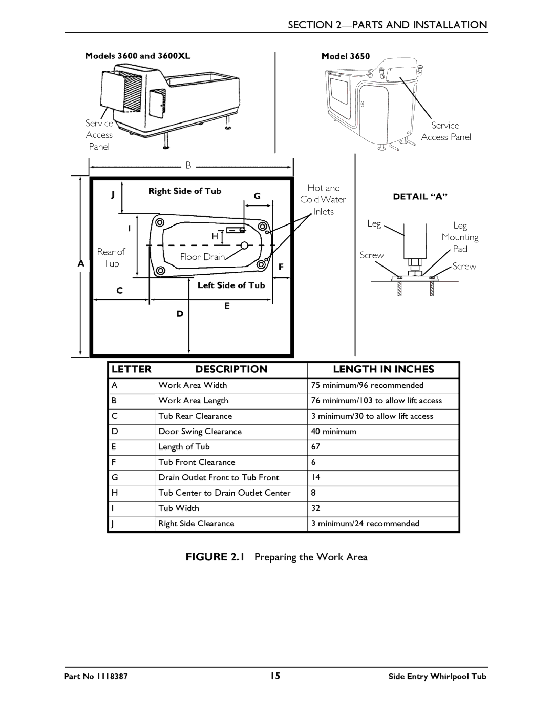
3650 specifications
Invacare is a renowned name in the healthcare industry, providing innovative solutions for individuals with mobility challenges. Among its notable offerings are the Invacare 3600, 3650, and 3600XL models, which are designed to improve the quality of life for users while ensuring ease of use and safety.The Invacare 3600 is engineered for users who require a reliable and comfortable wheelchair. It features a lightweight aluminum frame, which contributes to its portability and ease of maneuverability. The user-friendly design incorporates adjustable armrests and footrests, allowing for customized comfort tailored to individual needs. With a seat width of up to 20 inches, it accommodates various body types while maintaining stability. The Invacare 3600 also includes durable, puncture-resistant tires that are designed for both indoor and outdoor surfaces, ensuring users can navigate various terrains without hassle.
The Invacare 3650 offers even more advanced features, making it suitable for users who need enhanced support and comfort. This model boasts a higher weight capacity and a reinforced frame, allowing it to accommodate larger users without compromising safety. The 3650 also integrates a unique folding mechanism, making it incredibly easy to transport and store. Its adjustable backrest provides additional comfort for longer periods of sitting, while the breathable upholstery minimizes the risk of skin irritation.
For those requiring additional room and support, the Invacare 3600XL is the optimal choice. This model features an extra-wide seating area and a robust design that supports heavier users. The 3600XL includes enhanced stability features, such as a wider wheelbase and a reinforced chassis, ensuring safety during use. Like its counterparts, the 3600XL maintains a foldable structure for easy transport, but it also comes equipped with advanced shock-absorbing components that provide a smoother ride across various surfaces.
All three models utilize cutting-edge technologies designed to improve user experience. Features such as adjustable components, enhanced seating systems, and lightweight materials all contribute to a product range that prioritizes user comfort and safety. Invacare’s commitment to quality ensures these wheelchairs not only meet but exceed industry standards, making them a trusted choice for individuals with mobility challenges. With their combination of comfort, durability, and innovative design, the Invacare 3600, 3650, and 3600XL models stand out in the market, empowering users to navigate their environments with confidence and ease.

