PROCEDURE 8 | FWD WHEELCHAIRS |
F
W
D
W
H
E
E
L
3.Remove the three (3) hex bolts, spacers and locknuts that secure joystick mounting bracket to armrest plate.
4.Remove the phillips screw that secures the front of the armrest pad to the armrest plate.
5.Remove the phillips screw that secures the rear of the armrest pad and armrest insert to the armrest plate.
6.Remove the armrest pad from the armrest plate.
7.Remove the lug bolt, washers and locknut that secure the existing armrest plate to the seat frame assembly.
8.Repeat STEPS 4-7 for opposite side of wheelchair.
17.Install the three (3) hex bolts, spacers and locknuts that secure joystick mounting bracket to armrest plate.
18.Slide the joystick mounting tube through the joystick mounting bracket to the desired position.
19.Secure adjustment lock to joystick mounting tube by turning lever on adjustment lock.
REMOVING/INSTALLING MKIV CONTROLLER (FIGURE 10)
C H A I R S
9.Position armrest plate with joystick mounting holes on desired side of seat frame assembly and secure with lug bolt, washers and locknut. Refer to FIGURE 9.
10.Position armrest plate without joystick mounting holes on opposite side of seat frame assembly and secure with lug bolt, washers and locknut. Refer to FIGURE 9.
11.Position the armrest pad on the armrest plate.
12.Line up the mounting holes in the armrest insert, armrest plate and armrest pad.
13.Reinstall rear phillips screw through the armrest insert, armrest plate and armrest pad and tighten securely.
14.Reinstall the front phillips screw into the armrest plate and armrest pad and tighten securely.
15.Repeat STEPS
16.Install Loctite 242 onto the three (3) hex bolts.
WARNING
Replacement controller MUST be same part number as factory installed controller - Otherwise injury or damage may result.
Removing
1.If necessary, remove the rear shroud and rear compartment (if equipped). Refer to REMOVING/ INSTALLING SHROUDS in this procedure of the manual.
2.Disconnect the left/right motor leads and battery leads.
3.Remove the two (2) locknuts that secure the exist- ing MKIV controller and washer(s) to the wheelchair.
4.Remove existing MKIV controller from the wheelchair.
Installing
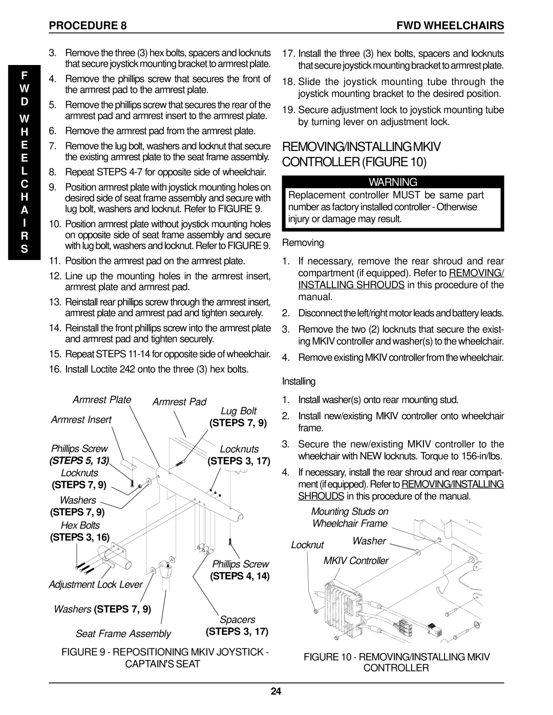
Armrest Plate | Armrest Pad | |
Armrest Insert | Lug Bolt | |
(STEPS 7, 9) | ||
| ||
Phillips Screw | Locknuts | |
(STEPS 5, 13) | (STEPS 3, 17) | |
Locknuts |
| |
(STEPS 7, 9) |
|
Washers
(STEPS 7, 9)
Hex Bolts
(STEPS 3, 16)
| Phillips Screw |
Adjustment Lock Lever | (STEPS 4, 14) |
| |
Washers (STEPS 7, 9) | Spacers |
| |
Seat Frame Assembly | (STEPS 3, 17) |
FIGURE 9 - REPOSITIONING MKIV JOYSTICK -
CAPTAIN’S SEAT
1.Install washer(s) onto rear mounting stud.
2.Install new/existing MKIV controller onto wheelchair frame.
3.Secure the new/existing MKIV controller to the wheelchair with NEW locknuts. Torque to
4.If necessary, install the rear shroud and rear compart- ment (if equipped). Refer to REMOVING/INSTALLING SHROUDS in this procedure of the manual.
Mounting Studs on
Wheelchair Frame
Locknut Washer
MKIV Controller
FIGURE 10 - REMOVING/INSTALLING MKIV
CONTROLLER
24