PROCEDURE 3 | FRONT RIGGINGS |
F
ADJUSTING REMOVABLE FOOTBOARD
Depth (FIGURE 8)
Removable
Flat
R
Footboard
Head
O N T
R
I
G G I N G S
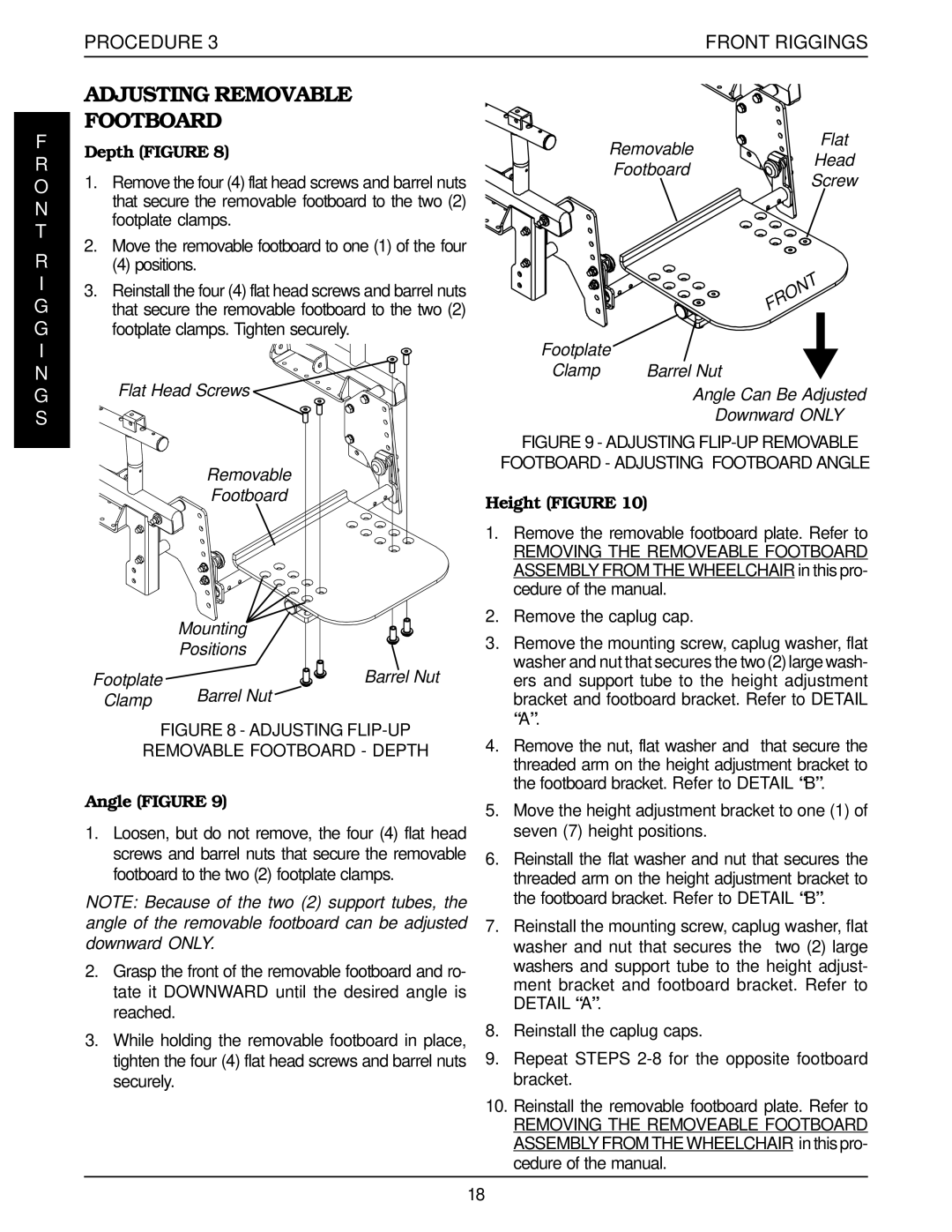
1.Remove the four (4) flat head screws and barrel nuts that secure the removable footboard to the two (2) footplate clamps.
2.Move the removable footboard to one (1) of the four
(4) positions.
3.Reinstall the four (4) flat head screws and barrel nuts that secure the removable footboard to the two (2) footplate clamps. Tighten securely.
Flat Head Screws
Removable
Footboard
Mounting
Positions
Footplate | Barrel Nut |
Clamp | Barrel Nut |
FIGURE 8 - ADJUSTING FLIP-UP
REMOVABLE FOOTBOARD - DEPTH
Angle (FIGURE 9)
1.Loosen, but do not remove, the four (4) flat head screws and barrel nuts that secure the removable footboard to the two (2) footplate clamps.
NOTE: Because of the two (2) support tubes, the angle of the removable footboard can be adjusted downward ONLY.
2.Grasp the front of the removable footboard and ro- tate it DOWNWARD until the desired angle is reached.
3.While holding the removable footboard in place, tighten the four (4) flat head screws and barrel nuts securely.
Screw
Footplate |
|
|
|
Clamp | Barrel Nut | ||
| Angle Can Be Adjusted | ||
| Downward ONLY | ||
FIGURE 9 - ADJUSTING FLIP-UP REMOVABLE
FOOTBOARD - ADJUSTING FOOTBOARD ANGLE
Height (FIGURE 10)
1.Remove the removable footboard plate. Refer to
REMOVING THE REMOVEABLE FOOTBOARD ASSEMBLY FROM THE WHEELCHAIR in this pro- cedure of the manual.
2.Remove the caplug cap.
3.Remove the mounting screw, caplug washer, flat washer and nut that secures the two (2) large wash- ers and support tube to the height adjustment bracket and footboard bracket. Refer to DETAIL “A”.
4.Remove the nut, flat washer and that secure the threaded arm on the height adjustment bracket to the footboard bracket. Refer to DETAIL “B”.
5.Move the height adjustment bracket to one (1) of seven (7) height positions.
6.Reinstall the flat washer and nut that secures the threaded arm on the height adjustment bracket to the footboard bracket. Refer to DETAIL “B”.
7.Reinstall the mounting screw, caplug washer, flat washer and nut that secures the two (2) large washers and support tube to the height adjust- ment bracket and footboard bracket. Refer to DETAIL “A”.
8.Reinstall the caplug caps.
9.Repeat STEPS
10.Reinstall the removable footboard plate. Refer to
REMOVING THE REMOVEABLE FOOTBOARD ASSEMBLY FROM THE WHEELCHAIR in this pro- cedure of the manual.
18
