Page 7
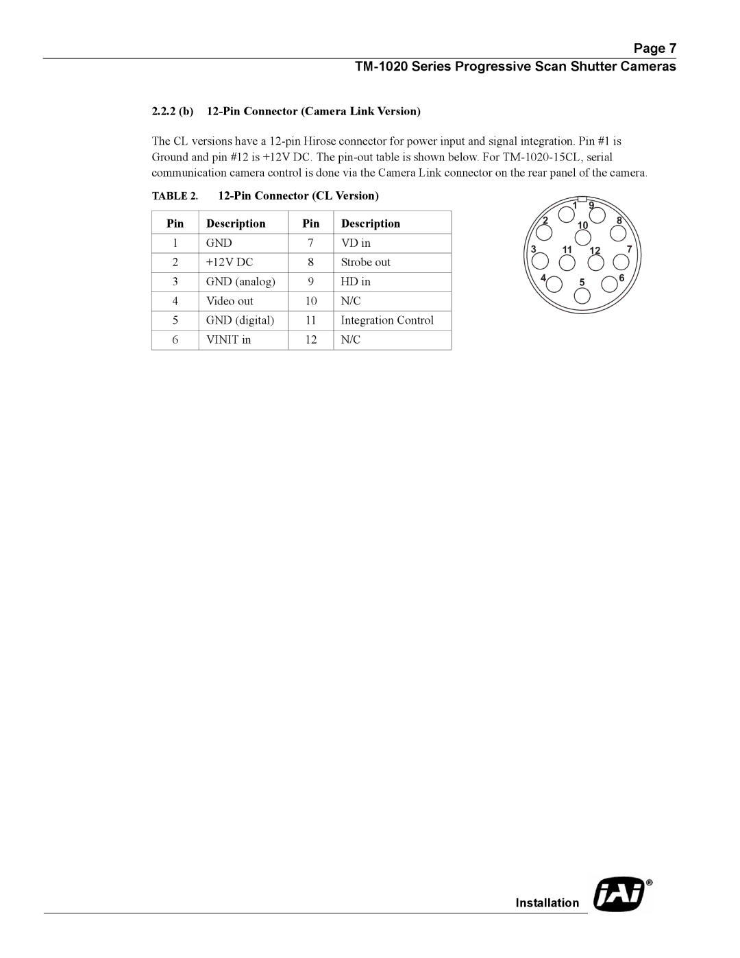
2.2.2 (b) 12-Pin Connector (Camera Link Version)
The CL versions have a
TABLE 2. |
|
| 1 |
|
| 9 |
| ||
|
|
|
| ||||||
|
|
|
|
|
|
|
| ||
|
|
|
|
| 10 |
|
| ||
Pin | Description | Pin | Description | 2 |
| 8 | |||
|
|
|
|
|
|
|
|
|
|
1 | GND | 7 | VD in | 3 | 11 |
|
| 12 | 7 |
|
|
|
|
|
| ||||
2 | +12V DC | 8 | Strobe out |
|
|
|
|
|
|
|
|
|
|
|
|
|
|
|
|
3 | GND (analog) | 9 | HD in | 4 | 5 |
|
| 6 | |
|
|
|
| ||||||
|
|
|
|
|
|
|
|
|
|
4 | Video out | 10 | N/C |
|
|
|
|
|
|
|
|
|
|
|
|
|
|
|
|
5 | GND (digital) | 11 | Integration Control |
|
|
|
|
|
|
|
|
|
|
|
|
|
|
|
|
6 | VINIT in | 12 | N/C |
|
|
|
|
|
|
|
|
|
|
|
|
|
|
|
|
Installation