Page 16
3Operation
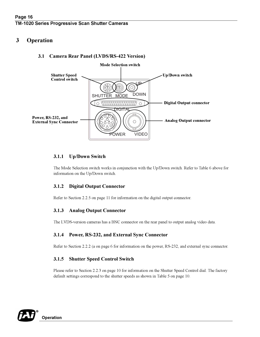
3.1Camera Rear Panel
Mode Selection switch
Shutter Speed
Control switch
8 | 9 | 01 | |
| 2 | ||
|
| 3 | |
7 |
| ||
| 6 | ||
| 4 | ||
|
| 5 |
|
Up/Down switch
F0 | 12 |
| |
E |
| 3 | |
D |
|
| 4 |
C |
|
| |
B |
| 6 | 5 |
A |
|
| |
9 |
| 7 |
|
8 |
| ||
SHUTTER MODE DOWN
Digital Output connector
DIGITAL
Power,
1 9
28
10
3 11 12 7
4 5 6
![]() Analog Output connector
Analog Output connector
POWER VIDEO
3.1.1Up/Down Switch
The Mode Selection switch works in conjunction with the Up/Down switch. Refer to Table 6 above for information on the Up/Down switch.
3.1.2Digital Output Connector
Refer to Section 2.2.5 on page 11 for information on the digital output connector.
3.1.3Analog Output Connector
The
3.1.4Power, RS-232, and External Sync Connector
Refer to Section 2.2.2 (a on page 6 for information on the power,
3.1.5Shutter Speed Control Switch
Please refer to Section 2.2.3 on page 10 for information on the Shutter Speed Control dial. The factory default settings correspond to the shutter speeds as shown in Table 5 on page 10.
Operation