Page 8
Installation
If you are building your own power cables, consult the
Attach the power cable to the connector. The
You may now plug the power cord into the 110V AC socket and power up the camera.
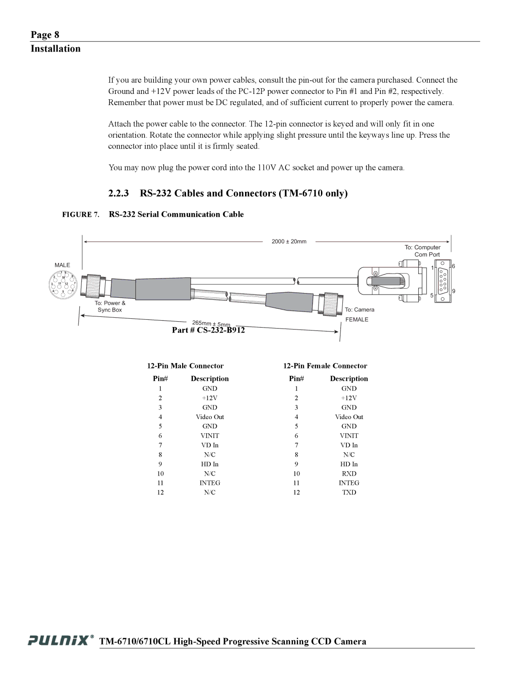
2.2.3RS-232 Cables and Connectors (TM-6710 only)
FIGURE 7. RS-232 Serial Communication Cable
MALE
| 1 | 9 |
|
2 | 10 | 8 | |
3 11 12 7
4 5 6
2000 ± 20mm
To: Power & |
|
|
|
Sync Box |
|
| To: Camera |
|
|
| FEMALE |
| Part # |
|
|
Pin# | Description | Pin# | Description |
1 | GND | 1 | GND |
2 | +12V | 2 | +12V |
3 | GND | 3 | GND |
4 | Video Out | 4 | Video Out |
5 | GND | 5 | GND |
6 | VINIT | 6 | VINIT |
7 | VD In | 7 | VD In |
8 | N/C | 8 | N/C |
9 | HD In | 9 | HD In |
10 | N/C | 10 | RXD |
11 | INTEG | 11 | INTEG |
12 | N/C | 12 | TXD |
To: Computer Com Port
1
5 ![]()
![]() 6
6
9