Page 3
Introduction
1.4 System Configuration
FIGURE 1. TM-6710 System Configuration
Figure 1 below presents a typical system configuration for the TM-6710 camera. Please see “Power Supply and Power Cable Setup” on page 7 for info on power supplies.
SHUTTER
9 | 0 | 1 |
|
|
| ||
8 |
| 2 | |
7 |
|
| 3 |
6 |
| 4 | |
5 |
| ||
|
|
| |
UP | D | E | 0 | 12 |
|
|
|
| 3 |
| |
VIDEO | C |
|
| 4 | POWER |
A |
| 65 | |||
| B |
|
|
|
|
|
| 9 | 8 | 7 |
|
|
|
|
| ||
DWN | MODE |
| |||
DIGITAL
P/N:
Multi Sync
Analog
Monitor
Digital cable: P/N 50DG-02LP
Frame Grabber
Board
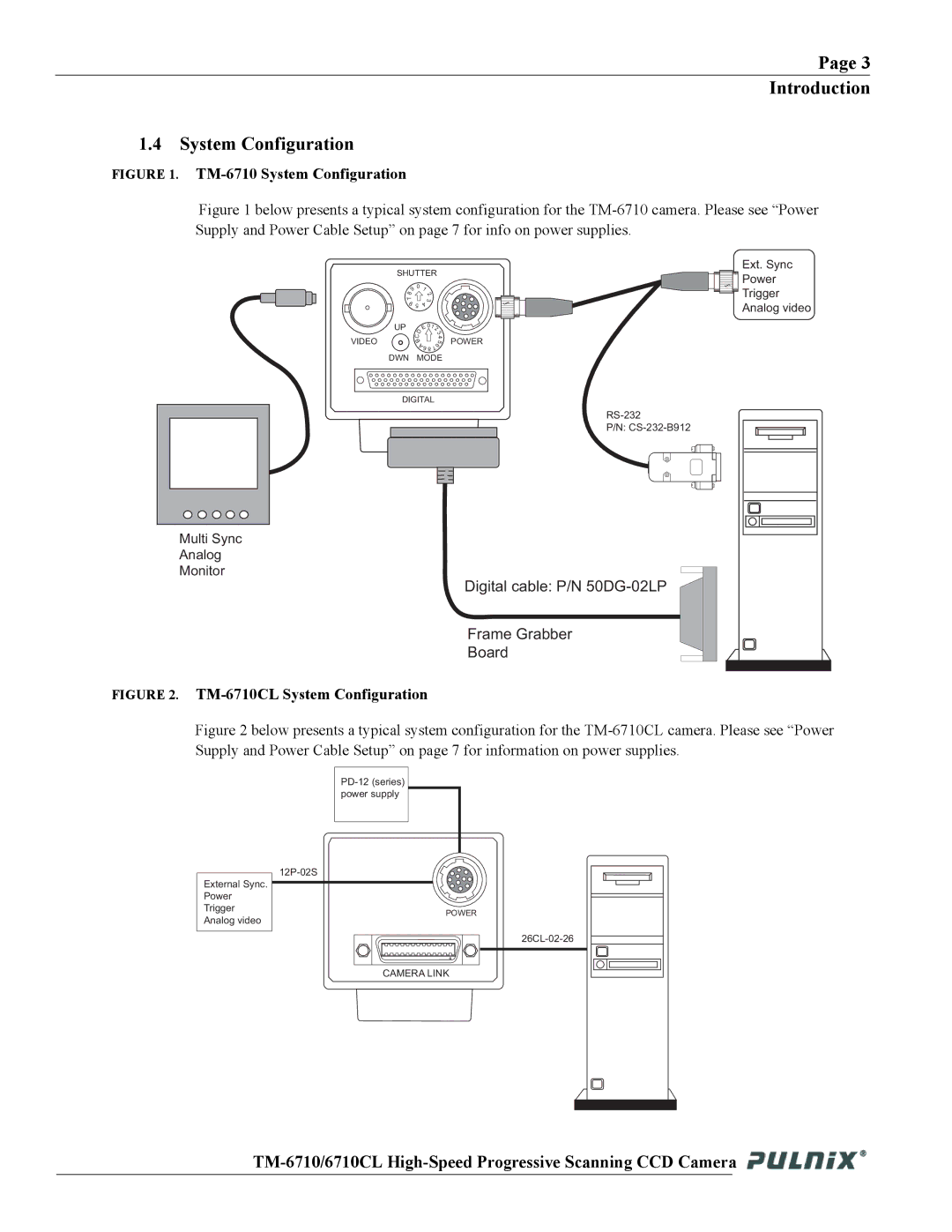
FIGURE 2. TM-6710CL System Configuration
Ext. Sync |
Power |
Trigger |
Analog video |
Figure 2 below presents a typical system configuration for the TM-6710CL camera. Please see “Power Supply and Power Cable Setup” on page 7 for information on power supplies.
External Sync. Power Trigger Analog video
POWER
CAMERA LINK
![]()