Page 20
Operation
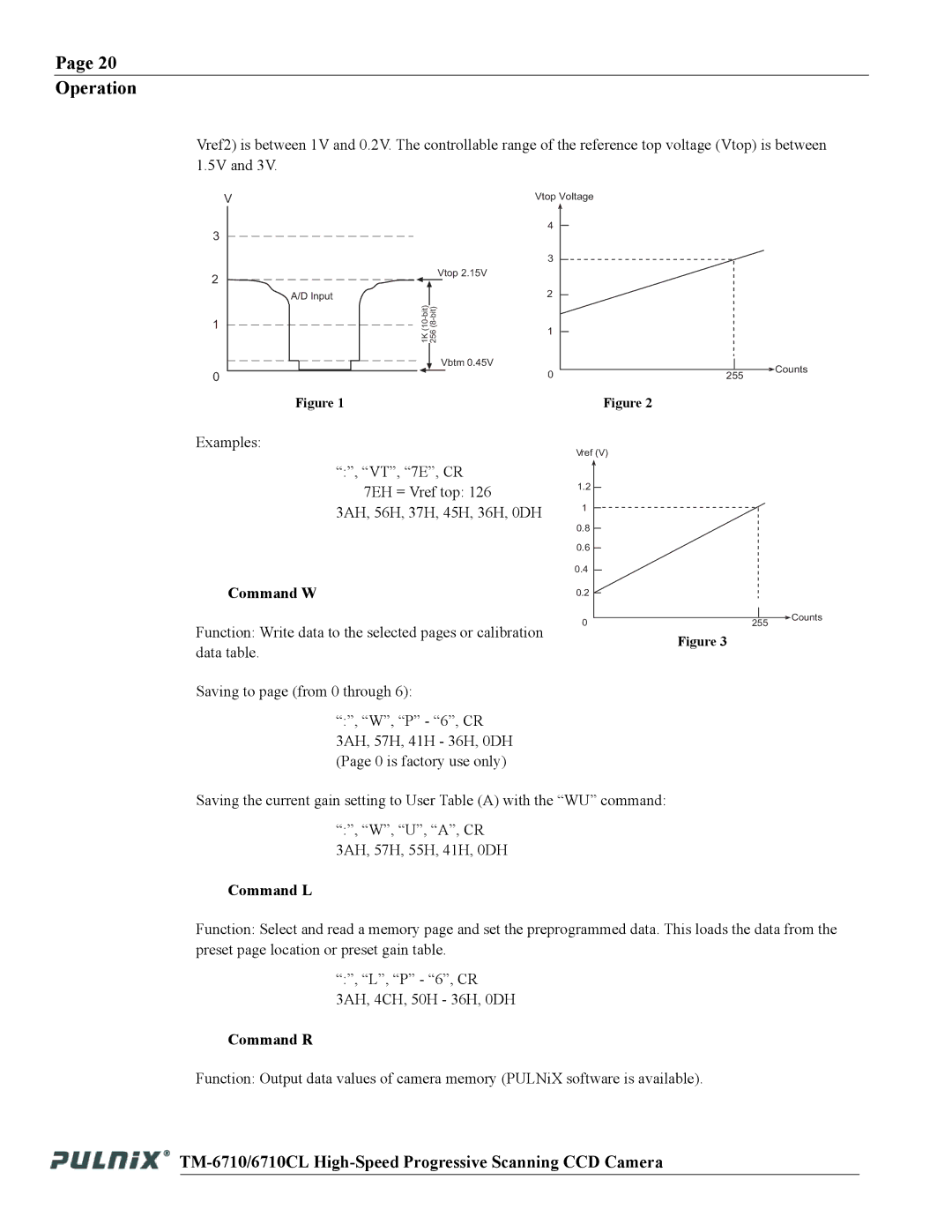
Vref2) is between 1V and 0.2V. The controllable range of the reference top voltage (Vtop) is between 1.5V and 3V.
V
3
2 |
|
| Vtop 2.15V | ||
|
|
|
|
| |
A/D Input |
|
|
| ||
1 |
| ||||
|
|
|
|
| |
|
|
|
|
|
|
Vbtm 0.45V
0
Figure 1
Vtop Voltage
4 |
|
3 |
|
2 |
|
1 |
|
0 | Counts |
255 |
Figure 2
Examples: | Vref (V) |
|
|
|
|
| |
“:”, “VT”, “7E”, CR |
|
|
|
7EH = Vref top: 126 | 1.2 |
|
|
|
|
| |
3AH, 56H, 37H, 45H, 36H, 0DH | 1 |
|
|
|
|
| |
| 0.8 |
|
|
| 0.6 |
|
|
| 0.4 |
|
|
Command W | 0.2 |
|
|
Function: Write data to the selected pages or calibration | 0 | 255 | Counts |
| |||
| Figure 3 |
| |
data table. |
|
| |
|
|
|
Saving to page (from 0 through 6):
“:”, “W”, “P” - “6”, CR 3AH, 57H, 41H - 36H, 0DH (Page 0 is factory use only)
Saving the current gain setting to User Table (A) with the “WU” command:
“:”, “W”, “U”, “A”, CR 3AH, 57H, 55H, 41H, 0DH
Command L
Function: Select and read a memory page and set the preprogrammed data. This loads the data from the preset page location or preset gain table.
“:”, “L”, “P” - “6”, CR 3AH, 4CH, 50H - 36H, 0DH
Command R
Function: Output data values of camera memory (PULNiX software is available).